


This article addresses . the situation when you believe that all EMC aspects are under control since you have applied regular EMC standards the way you normally do – and then you get surprised by finding that you have electromagnetic interference (EMI) in the field operation, causing troubles for your customers. And even worse: your customers get the surprise first before you know anything, leaving you in the hot spot of explaining why this is happening.
So, all your apparatuses have passed the applied EMC tests, but it will not work in the real world. What happened? I will give some examples showing what might happen when you are introducing new technology.
It is in general not a problem to handle EMC in a regular way for new designs that are refining and improving existing concepts. We have a number (a ridiculously large number, but still) of EMC standards covering the major known problem areas. They are not perfect, but they keep EMI issues at a relatively low level.
The situation may be different when we are making new design concepts that are out of bounds of our traditional thinking. We then get surprised by new unintentional combinations of cunning products and new interaction with EMI threats. I list a set of examples under the following headers. My intention is to list them in this way, making groups of different types of surprises.
Added threats
In this scenario, we consider a product that is moved out of its normal environment. A mature type of product has been sold for some time, and the EMC performance is verified using the EMC standard intended for the environment. Then we develop a new market scope. We realize that the product can be used by new customers in a new unexplored segment!
Example: domestic outdoor lighting is placed in the garden instead of indoors. We use the same standard components as for the indoor product, and apply the same standard. It is still a domestic product, so no need to look for something else. However, the installation is very different! This way, the lighting system is placed close to the soil – making it a virtual grounding rod for your house. When a lightning strike induces a surge in the public mains, that pulse will find a way through your house and down to the soil ground.
In summary, the manufacturer has probably applied a regular EMC standard for domestic environment, but they did most likely not include this new risk scenario in their test setup.
New electromagnetic neighbors
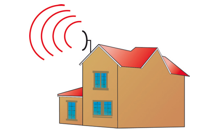
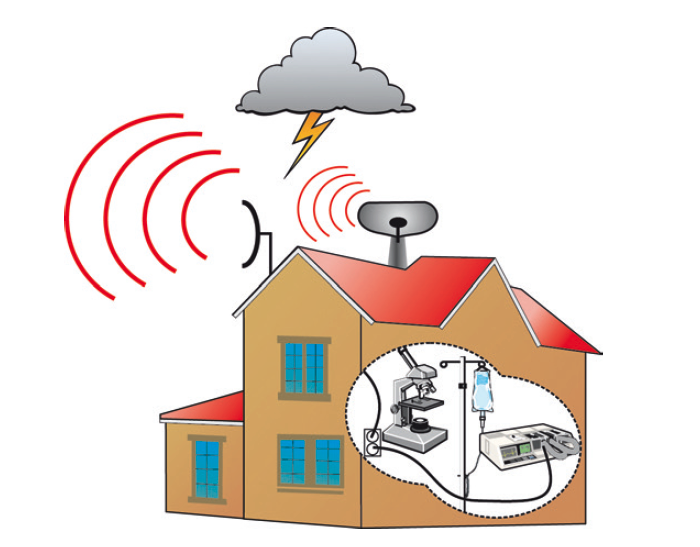
The figures 1 and 2 show a general situation, where a radio communication system is placed on a roof to get good range. This looks all fine, until we look around and discover that:
a) we have a lightning threat to handle.
b) the building contains research equipment sensible to RF, and the side lobes from the radio might interfere with it.
Another example I encountered many years ago was a car workshop that was placed adjacent to a medical care centre. When the welding of cars was going on, they had a very hard time making the EKG equipment work. The RF field went right through the wall and into the sensors on the patient. The solution? Someone had to move, or they were forced to work in shifts with a time schedule. Building a shielded workshop was not an option…
A similar situation came to the surface at Chalmers in Gothenburg, who was about to purchase a new top of the line electron microscope. These are highly sensitive to power frequency magnetic fields, and we were struggling to find the different sources and press them down. In the end, we found that the remaining field source was one of the neighbors to Chalmers: the electric tram passing in the tunnle underneath it. The main problem was the – low but still significant – Common Mode (CM) current propagating in the tunnel. A solution to this problem had been presented (actually by my predecessor Ulf Nilsson) several years prior to this work. But no one did anything about it at that time (when it would have been comparatively cheap to do it) and rebulding it this time was never brought up. The solution? This time, no one could move (!), so Chalmers had to schedule sensitive experiments during night. In terms of EMC compliance, the tram company had done nothing wrong since CE marking does not apply to fixed installations and the used components are very likely to be CE marked. These low frequency fields are outside the scope of product standards, so the EMI problem is not found until you are on site. This actually means that strictly the tram system is violating the EMC directive, since it simply says that interfernce is not allowed and you are supposed to fix it.

New functionality
In figures 3 and 4, we see a product (the headset) in different operating configurations. In the stand-alone mode, we do not have any connecting wires, and consequently no threats related to conducted RF currents or transients.
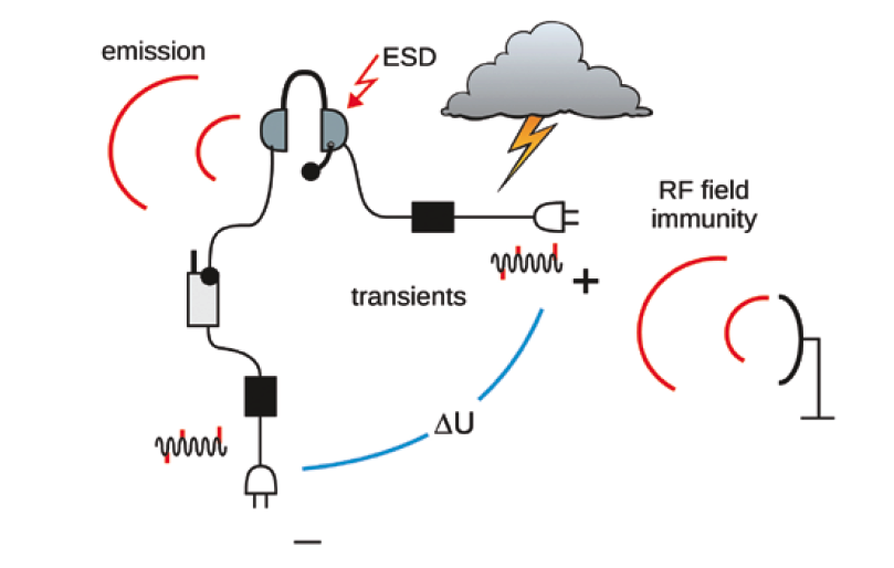
When we change the configuration to include several other components into a more complex system, the EMI risks are enhanced since we now have new coupling paths for external threats into the system. Note that each apparatus may very well meet ordinary CE marking EMC requirements on their own. But if each supplier has not forseen a scenario as the one in figure 4 but merely performed EMC testing with e.g. isolated artificial loads, the system is most likely to encounter failures in real life operation.
This is a typical example of the inequality equation:
 Replacement of older robust electronics
For this type of surprise, I give one short example. Traditionally, road illumination system (road lights) have been designed using high pressure sodium lamps or mercury lamps. These were inherently rather robust and durable to transients. With the introduction of LED lights, the susceptibility to surges was drastically greater. The ordinary EMC standard for professional lighting equipment was not sufficient (nobody had noticed before, since not much happened) and enhancement of the requirements had to be done by adding stricter requirements. On top of that, the need for modifications was quite urgent, since the consequence of a failure would be that when driving in a thunderstorm you would suddenly find yourself drivning on a pitch dark road.
Combination of product areas
Another type of surprise may arise when you are combining two product areas that normally are not connected together. Let us take the example of cars and public mains (in this case DC charging is also included).
Today, the requirements on the AC port charging is covered in the vehicle type approval as per UN ECE R10. The regulation has in essence copied the requirements for a domestic product, which is quite elegant. Both types of products share the same grid. So that should be fine!
However: the standard requirement on power frequency harmonics emission (that e.g. prevents transformers and neutral leads from overheating) is rather generous, and I doubt that the local grid operator is expecting 50 – 100 cars (who might just barely meet the limits) to be charged for 5 hours daily at max rated current? It might work in a strong grid, but what about a weak net? Maybe this will work if the cars are designed with a large margin but this is a future issue since we do not have that many electric cars yet.
Another aspect is that cars are very different than other AC loads. They have an additional signalling interface with the house called the Control Pilot. This signal checks the power grid quality. Well, overheating in the socket is not included, but protective earth connection and fuse rating is (at least up to the adapter box you may have lying on the ground). In the regulations, there are no immunity requirements on this interface. But, everyone working with EMC and AC grids knows that transients and other threats are quite common here. On top of that, the consequence of a disruption in this signal is that you may not have any charged batteries in the morning…So, the car manufacturers have to be prepared for this. Type approval does not mean that you have sufficient product quality.
On the DC charging side, the situation is much different. There is no AC grid provider urging the car industry to meet their needs, leaving the field open for tailoring of requirements in the UN regulation. If we look into this document, we find EMC requirements on the DC port in terms of conducted emission, fast transients and surges. OK, that sounds nice. However, these requirements are not mandatory. There are no requirements at all on DC cables that are shorter than 30 m. Who came up with the idea that a 29 m long cable is not an efficient potential RF transmitter?
From the beginning, the vehicle type approval was mainly focussed on limiting EMI problems for third parties – the adjacent car or pedestrian. If someone builds a poor car that disturbs itself, it will be the manufaturer’s problem. For that reason, conducted emission has never been a regulatory issue. It seems like this reasoning has been extrapolated to the DC fast charging, since it is an extension of the car high voltage grid.
But this time it is different, because the car is connected to its surrounding – a new situation we never had before. And the cable is much longer than the car, making it a potential antenna at frequencies not covered by the present radiated emission measurements. For this reason, the car manufacturers have been making additional measures to cover this gap in the requirements.
Recommended approach
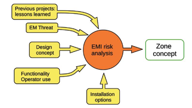
In order to reduce the risk of running into problems such as I have described, we need a tool in our development project. If I would have to pick one single project activity for EMC, it would be the EMI risk analysis (figure 5). This activity shall be made early in the project – in the concept phase. When applying this analysis on a new design concept, we challenge the fantasy and ingenuity of all engaged engineers – what might happen, and how? It will not be a simple checkbox in the project manager’s chart (it never should be, by the way). Do not rely on CE marking doing the job for you at all times!
In addition to regular analysis, we now focus on a set of specific questions:
- Who are our electromagnetic neighbors?
- Do we combine equipment in a fashion that we have not done before?
- Do we use new components that are more sensitive?
- Do we need to handle higher levels of threats?
If we find some changes, we document them and make adjustments on the Zoning Concept that will guide the design work in the following steps. The important thing is to have respect for the EMI risks and not rush into things, leaving out this aspect just because “we do not really have the time for this, and these fields and pulses etc are not my department”.
Lennart Hasselgren, Lic Eng. EMC Services
lennart.hasselgren@emcservices.se
If you have ideas and comments on this article, please feel free to mail me! Some might also recognize my short examples, and if you want to add something that would be an interesting talk.