

This article . is a part of a series of texts that will deal with the EMC challenge in terms of project management and the practical EMC activities at different stages in the project flow.
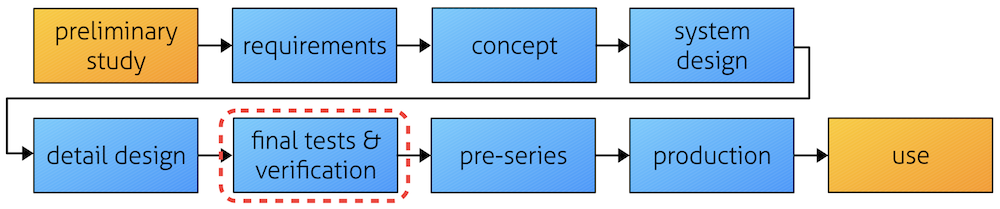
Different companies all have their own way of describing their project flow, so to keep it simple we will use the labels as given in Figure 1. We can call it a generic project flow. The picture only describes the basic outline of the work packages. These articles will describe the actual practical work we want to do in the project to “make EMC work” in a time- and cost-efficient way. Each part of our series will fill in the details for each part piece by piece.
This is the 6th part – Final EMC testing – in our process.
We have previously looked at the EM environment, requirements, possible disturbance risks, and we have designed prototypes including a set of pre-compliance testing. This work has now resulted in a final product that is ready for verification. We will here get the final receipt that everything is designed as requested. With all our preparations, we will hopefully not get any surprises. EMI risks are analyzed, pre-compliance testing has been performed and we are ready to go to the Final EMC Test.
The scope of final EMC testing
Attitude to testing
To begin with, EMC testing is made using the EMC requirements that are based on customer needs, or at least the legal requirements. It is not a cursed tedious activity that has to be done as quick as possible. You can regard the EMC testing as the electrical crash test for electronics. Now is the time when you will find out if the product is robust enough! So, it is a golden opportunity to get critical information about the product. If you are spending so much money on this test and its preparation, make sure you get the most out of it.
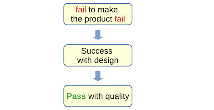
The aim is to make robust products matching customer expectations. So, when testing you should strive at making the product fail. Be as tough as possible, but within requirements. When I have failed to make the product fail, I have succeeded with my design = Pass (see Figure 2)
The prepared path for the testing
There are several manufacturers that rush into final verification testing with very poor preparations, making the failure rate at EMC testing quite high. In the previous articles I have described a multitude of activities that are to be performed before rushing into the EMC test chamber. The major value in the work prior to testing lies in
- Requirement identification
- EMI risk analysis
- Pre-compliance testing
There is a huge potential in the industry to improve these matters. With correct preparations, we know what to test, how to make test on the specific product, and also how much testing is actually needed.
Test setup principles and comments
There is a large amount of test methods for EMC, being described in various test standards. Instead of going through all of them (gasp), I will just make a rough grouping of their scope (and yes, it will be very rough) to make some general comments. We can group testing in two major groups (for apparatus and components).
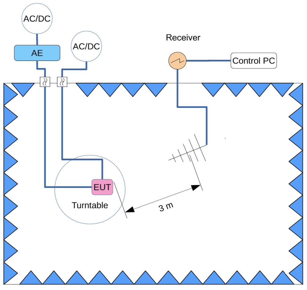
The industrial and domestic group (which also include marine and railway equipment etc.) use EN/IEC standards for testing including CISPR16 (EN 55016) setups. An example of radiated emission setup is shown in Figure 3, with a tabletop configuration on a turntable. The EUT (Equipment Under Test) is placed 80 cm above the Ground Reference Plane (GRP). The key aspects here are to measure the emission from several angles to find the worst case. The EUT is communicating with Auxiliary Equipment (AE) via a filtered inlet.
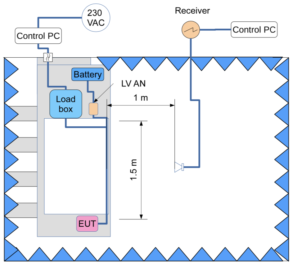
In Figure 4, we find the automotive component setup as given in CISPR 25 (EN 55025), which is very similar to military and avionic setups (besides all details on networks and cable lengths etc.). Here, the EUT and the wiring is placed 5 cm above the GRP, which is assumed to reflect the impact of the vehicle chassis. The key aspect here is to measure very low emission values in a specified direction (some specify 3 angles, but still) at close range with a specified wiring length. The EUT (some call it Device Under Test, DUT) is communicating with a loadbox. Immunity testing is covered by a set of ISO standards.
The AE and the loadbox is the same thing. They include all interfaces – except power supply – to the EUT that is needed for proper operation and monitoring. Two words are used, because the industry cannot agree on using one. Same thing with the EUT vs DUT. The consequence of the different approaches is among many other things that
- In the Non-automotive industry, the aim is to keep all the AE trouble outside the chamber. Cables will be long anyhow, so make it simple and move the non-EUT gadgets out of the way.
- In the Automotive industry, the aim is to keep all the loadbox trouble inside the chamber. It is very important to keep all wiring at 1.5 m length (1.7 m including terminations), so there will be a lot more focus on building robust loadboxes. This aspect is often missed by new players on the automotive market.
Bench testing is a separate issue that is also critical. These immunity tests are often destructive. Transient tests often provide the high score in damaging both EUT and the AE. If the AE is damaged, the test is inconclusive since we do not know how the EUT would respond with an intact AE (that might have absorbed the pulse, protecting the EUT).
On top of this, we also have complete vehicle test methods and on site measurements – but the number of pages are limited by the editor.
Performing the test
How much do we need to test?
Let us say we have a rather complex test object that includes
- A large amount of signal cables
- Several operating modes
- Several hardware variants that cannot be assembled in one single EUT
- Different interface options and software
- Different power supply conditions
If we would make a strict EMC test with everything included, we could be testing for several weeks and drown in data. In order to optimize our efforts, we make a selection of worst-case hardware configurations, operating modes, and other simplifications that are based on our knowledge of the product. All this is derived and stored in our EMI risk analysis and in the EMC test plan (or better name: verification plan). It might be argued that if you order an accredited test, you will not do these optimizations, since everything is strictly specified. That is not the case, because it is up to you to define your product and how it shall be operating in detail. In addition, the test standards themselves provide optional choices within the scope of the accreditation. It is true, though, that you can not cut the corners so much, compared to making a tailored test plan based on engineering assessments.
Most of all, we only need to do the test once. We have made a set of pre-tests that have given information about the EMC performance, and possibly also information about what the worst-case settings are. Reduction of re-testing is one of the best money savers of them all.
Concise testing and monitoring
With the experience from pre-compliance testing we are well prepared for the verification test having:
- Cables of correct type and length
- High quality connections to the chamber wall
- Optimized software settings.
- Robust AE/loadbox
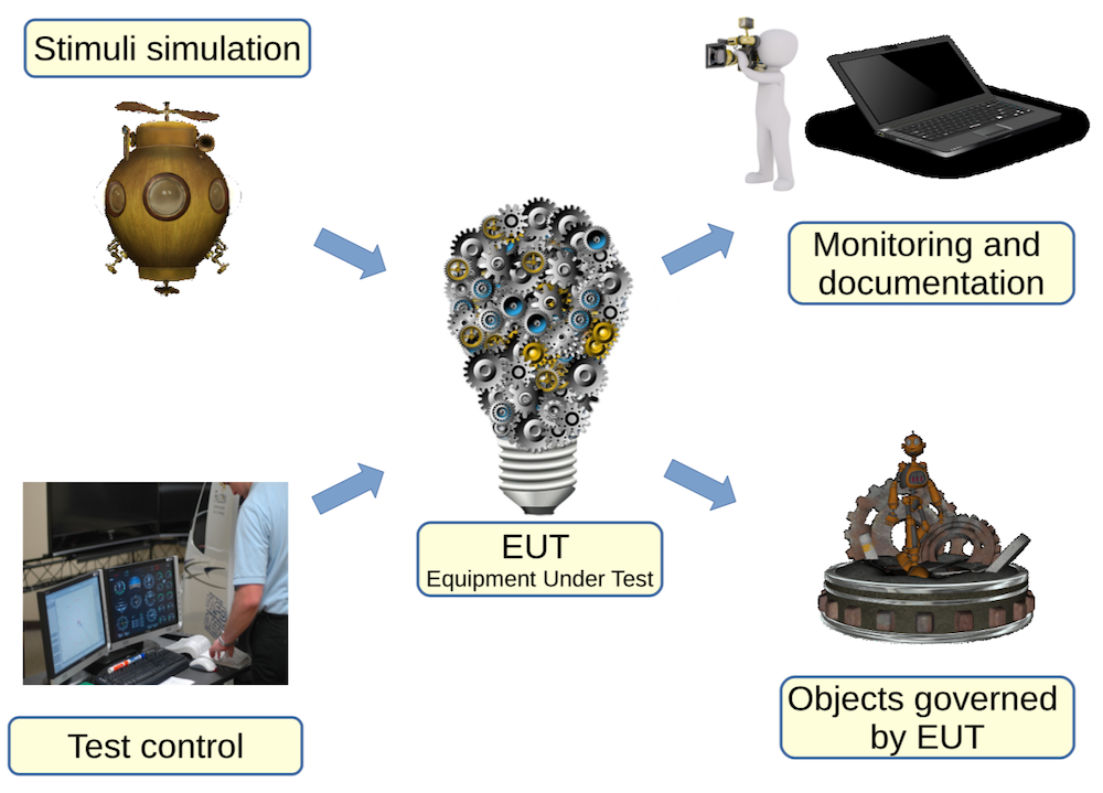
Not the least, we want to get a high quality of our EUT performance monitoring. If testing goes fine, we will only monitor normal product behavior, and nothing special happens. But: is nothing happening because your monitoring is poor?Or in other words: are you sure you have a thorough observability of expected – and unexpected! – behavior? The test quality depends on the stimuli equipment, monitoring equipment, EUT loads – and also on the EMC lab quality (see Figure 5). It is somewhat interesting to note that accreditation and quality control is very important for the EMC lab, but not that much discussed concerning the other three critical aspects. Blind testing is useless testing.
Be prepared for surprises
Troubleshooting: this activity will hopefully not occur at this stage. If it does, however, we shall use all the tools that are available from previous design stages. Most of all: the EMC zone description, which will tell us where the leakage is most likely to occur. The value of the pre-compliance testing will now be even higher. Did we keep some of the modifications as safeguards for the final testing? It is always good to have some aces up your sleeve.
Assessment of the test results
Using the test results effectively
All the simplifications that we have made for the verification test to make it realistic means that we have not performed the testing strictly according to the letter in the standards. The technical quality is however not compromised, and we now have a task of describing that we have a compliance documentation with a reduced and optimized testing result. This is made in an analysis document that we here call the EMC Verification Report.
In addition, we might have several other complications:
- It did not work that well in the test, but we know what to change. Do we have to repeat the complete test suite? Or can we make a comment in the analysis only?
- Testing has been made on several versions of the EUT with different modifications, and possibly also in different labs
- Some tests were not made according to specification, but in another cunning way that has the same assumed test quality
The meaning with the different documents
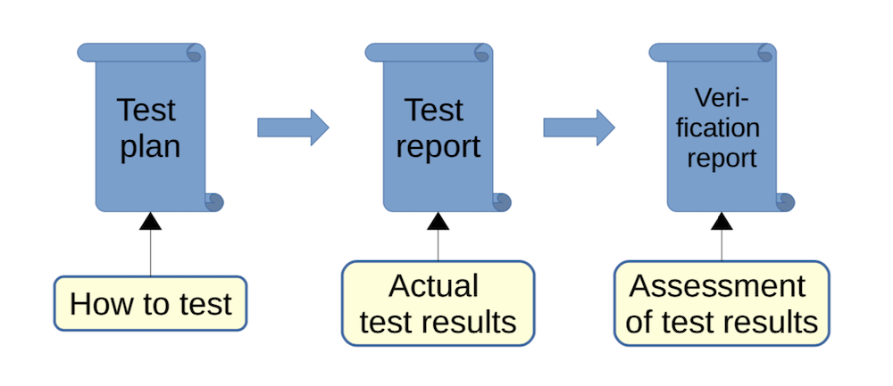
It is important to understand the meaning of the three types of documents in Figure 6. The verification plan tells you how the test shall be made. It does not necessarily mean that it happened that way in real life. The EMC test report tells you what actually happened and nothing more. No serious laboratory will add their own assessments (or yours) in such a document – it shall not contain any analysis. The EMC verification report sums it all up: why the simplifications are valid, how may EUTs were tested and how you can sum the results together. It can also refer to other analysis documents, or test results performed by sub-suppliers.
Sign-off and approval documentation
Converting the test results to compliance folder records
All the documents we have generated are now collected for the final review and company approval. They are presented to the responsible design or product manager, and the final sign-off is made according to the company procedure. On top of that, the official statement – type approval by authority or own Declaration of Conformity – is generated for regulatory requirements.
In summary, the compliance folder will contain the following:
- EMC verification plan (test plan)
- EMC test records
- EMC verification report
- Type approvals (if relevant)
- Declaration of Conformity (DoC)
- Compliance sign-off
- Text materials for the additional documentation below
Additional documentation needed
The data sheet: this is where you normally look for information about what temperature it can operate in, IP class, operating voltages, accuracy etc. EMC specifications is a natural extension of these data. I want to know how high transients it can endure, emission levels etc., and the product specification is the place where I as a customer want to find this information – all at the same place. If you think the user is interested, you can be more specific. Otherwise, stating the applied product standard is well enough. Do not list the test methods (like EN 61000-4-5) without test levels and obtained performance criteria; that is of no value at all.
Operator instructions. The user must be informed about what electromagnetic environment that is intended (like marine environment), and also how to use the product without violating EMC performance. Such instruction could be to use an ESD wrist strap when doing service on the inside among other things.
Installation instructions. When you have designed your product, you have made an assumption on how the product will be installed, e.g. cable lengths, power supply etc. This information shall be forwarded to the customer to avoid misunderstandings. This is your safeguard if products are broken due to harsh environments that were not within the scope.
Lessons learned
How do we remember this?
The standard procedure in many companies is to rush on to the next project, because we are in a hurry. But the reason for being in a hurry may be that we are not using our experiences from previous projects in an effective way – because we can not find the information. It is stored in several individual brains… So, we should take a step back and look at what happened this time and write it down.
Which design modifications worked? Did not work? Are some designs overkill? This is valuable information to future design reviews.
We worked quite a lot with pre-compliance testing and built several practical gadgets. Keep a Golden Box with AE, gadgets that you know will work in the lab. These have been tested in the pre-compliance testing – proven in battle.
Did we find new relevant tests or market requirements during the project? Should they be transferred into the templates?
Input and output
As a summary, we find the following interface conditions to the other parts of the project flow.
Input from previous work:
- EMC verification plan
- Relevant and testable EUT (should be the finished product)
- Pre-compliance test results (indicating worst case selections etc)
- Robust stimuli and monitoring equipment
Output from this stage:
- EMC test reports
- EMC verification report
- Compliance sign-off
- Type approvals (if relevant)
- Declaration of Conformity (DoC)
- Compliance matrix
- Updated with status from the tests
- Lessons learned document
Closing remark
With this test phase, we have now come to a conclusion that our product is compliant with the relevant EMC requirements and ready for sale! That is great, and the work has been performed with high quality at the same time as costs were held down, and time schedule was kept.
Most of all, we only needed to do the EMC verification test once! This is a sweet dream for many project leaders, and I have seen it come true at rare occasions. Reduction of re-testing is one of the most cost-effective measures of them all. But to reach that goal we need to be well prepared – in the way the complete set of these articles are describing. It is not a one-off activity, but needs a process driven workflow. EMC testing and project delays are kept down with EMC analysis using trained and experienced engineers.
Because of the name of this article, you might think we are done now, but this is often not true. More work will most likely be added, as will be described in the next article…
Lennart Hasselgren, Lic Eng.
EMC Services, lennart@emcservices.se If you have ideas and comments on this article, please feel free to mail me! Some might also recognize my short examples, and if you want to add something that would be an interesting talk.