
We demonstrate . a novel Eddy current Destructive Testing (DT) method for determining the electromagnetic interference (EMI) shielding effectiveness (SE) of an electrically conductive material. The DT approach is based on Halbach principle of array magnetic field to creating further improvement of its sensitivity and reduction of electromagnetic (EM) interactions with nearby systems. The simulation results show that the DT method has better performance than the mutual inductance method (mutual inductance of two coils). We use COMSOL Multiphysics RF Module 6.1 for design and validation of the DT.
Index Terms – EMI shielding effectiveness (SE), non-destructive testing (NDT) method, Eddy current, Halbach principle, Graphene
I. SCOPE AND INTRODUCTION
An AC-driven coil induces magnetic field that interacts with a conductive surface and produces Eddy current on the surface. If the surface is then brought close to the coil, the secondary magnetic field generated by the Eddy current opposes the primary magnetic field and thus affects the current and voltage flowing in the coil, resulting in changes in impedance of the coil. The secondary magnetic field will vary if there is a change in the electrical conductivity, magnetic permeability, or thickness of the surface. The change in the field will be picked up by the coil. The method is also called, non-destructive testing (NDT) method [1] – [7].
Nowadays, on-road charger systems based on inductive charging are becoming increasingly popular with remote electric vehicles [8]. However, such systems cause electromagnetic field (EM) leakage which can produce unwanted effects throughout the body, communication systems etc. Many studies have been conducted on the EM shielding issues [9][10].
We propose a novel Eddy current Destructive Testing (DT) method, that uses a specially designed mutual inductance system with the receiver part mimicking a Halbach configuration. A Halbach array is a special arrangement of permanent magnets that augments the magnetic field on one side of the array while cancelling the field on the other side [11] – [13].
The proposed Halbach array is arranged with a spatially rotating magnetic field vector which has the effect of cancelling the field out on both sides. The aim is to reduce the Eddy current and improve the sensitivity of the system and minimize interactions with other systems. COMSOL Multiphysics 6.1 RF Module software will be used to design and verify the model.
II. METHODS, COMSOL SIMULATION AND RESULTS
A. A MUTUAL INDUCTANCE SYSTEM
Fig. 1(a)-1(d) illustrates a mutual inductance of two coils with simulation results, using the Maxwell’s equations for electric and magnetic fields in COMSOL Multiphysics RF Module 6.1. Fig. 1(a) shows the coils placed within a sphere (non-reflecting domain, Perfectly Matched Layer PLM, COMSOL). The coils are of the same diameter (1 cm). The coils are aligned with each other with 2 cm in-between them. Fig. 1(b) illustrates a splitring resonator – based coil with an inductor (L = 1 nH) and the Port. The signal being applied to the Port of the lower coil is sinus (1 V, ON).
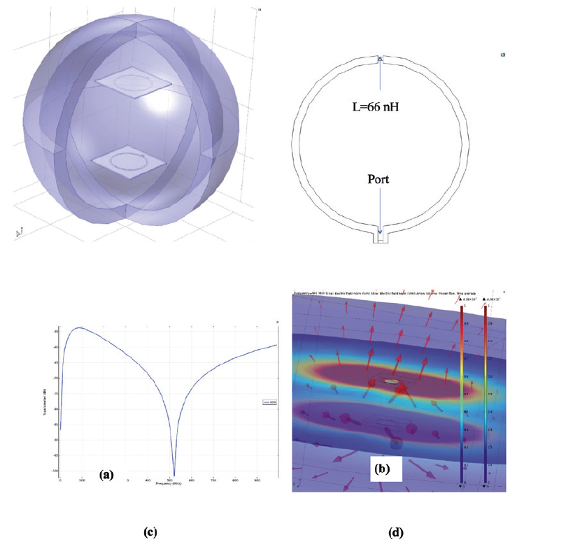
The upper coil is not exited (OFF). Fig. 1(c) shows the S-parameter simulation result for the system along frequency (1 MHz – 1 GHz). Fig. 1(d) shows the electric field distribution (colour bars, normalised electric field V/m) and the power with arrows at frequency 991 MHz.
B. THE HALBACH ARRAY V.S. A SINGLE COIL
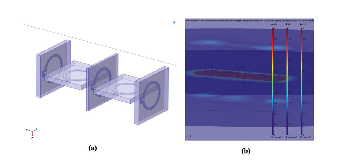
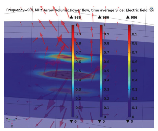
Fig. 2(a) illustrates the proposed Halbach array of five set of coils each of which consists of three equal coils. The electric field is weak at distance of 2 cm (Fig. 2(b)). The signal being applied to the ports from left to right: (-1 V, -1 V, -1 V), (1 V, 1 V, 1 V), (1 V, -1 V, 1 V), (-1 V, -1 V, -1 V), (-1 V, -1 V, -1 V). That is quite different from the results obtained for a single coil (compare Fig. 2 with Fig. 3). Fig. 3 shows simulated distribution of electric fields on planes chosen at a distance from an exited coil.
C. THE DT METHOD
Fig. 4a illustrates the proposed DT. The Halbach array (Fig. 2) is also configured as in Fig. 4b with some of coils rotated 90Åã in specific directions to achieve high performance. Fig. 4c shows the weak field around the Halbach array. A comparison of S-parameters of the single coil 1 – coil set 6 (S61, between the transmitter (single) coil and the middle coil set in the Halbach configuration) and the coil 1- coil sets 2-5 (S21, S31, S41, S51 in the Halbach configuration) is shown in Fig. 4d.
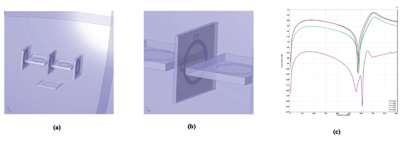
Fig. 4(a)-(c). Illustrates, (a) the DT including the single coil and the Halbach array, (b) the middle coil set with the middle coil rotated 90° upwards, and (c) S-parameters, S21, S31, S41, S51, S61, where 1, 2, 3, 4, 5, and 6 are index denoting the coils: single coil 1, coil sets 2-5 (from left to right) with the middle coil set 6 of the Halbach array, respectively. The ports of the coils which belong to the Halbach array are set to OFF, while the single coil is set to ON.
The DT showed the same S1i-parameters (where i = 2, 3, 4, 5) responses as for the mutual inductance configuration (compare Fig. 1c with Fig. 4c). The signal is more attenuated (S61) due to the alignment and placement of the middle set in the configuration.
D. SIMULATION APPLICATION
Fig. 5(a)-(d) shows two cases. In the first case a copper sheet is placed in between the coils in the mutual inductance configuration (Fig. 5(a)-(b)) and in the second case a graphene sheet is replaced (Fig. 5(c)-(d)). The results of S-parameters indicate a higher attenuation along frequency for the copper sheet (compare Fig. 5(b) to Fig. 5(d)). In Fig. 6(a)-6(b), the S-parameters of the copper and graphene sheets are plotted for the DT, respectively.
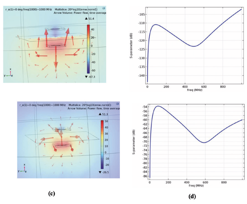
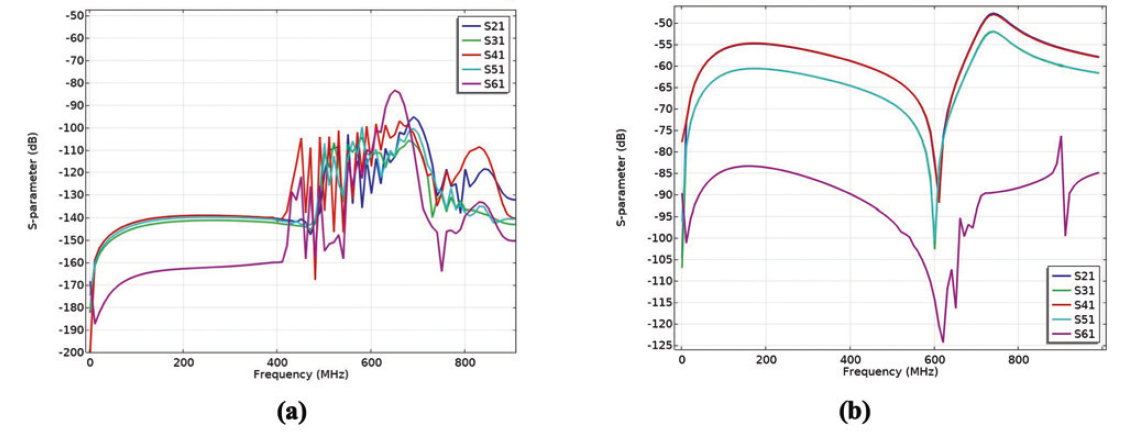
Fig. 6(a)-6(b). Transmission coefficients (S21, S31, S41, S51, S61) of the proposed DT configuration.
III. CONCLUSION
A DT method for determining the EMI shielding effectiveness of an electrically conductive material was developed. It works with no magnetic flux from the coil array in contrast to the NDT method, which uses the magnetic flux from a coil to generate Eddy current on a conductive surface. The results show that the DT has better performance than the mutual inductance method. The proposed method was validated by correlating the electric fields obtained from simulations. Some improvements are considered by the author:
(1) Optimizing the proposed DT.
(2) Formulation of a new quantum mechanical theory to identify the physical properties (permeability, conductivity) of a graphene sheet in presence of magnetic field. Considering the temporal response of electrons in Landau levels in the graphene sheet (by further developing the scheme of studying time-dependent first-principle Schr.dinger equation).
(3) Developing high-strength surface coatings of graphene mixed with various biodegradable materials (cellulose-based, carbon nanotubes CNTs, bio-based polymers PLA, etc.).
(4) Developing a new statistical theory for the analysis of the behaviour of conductive composites under EMI SE test.
Zackary Chiragwandi EMC Services Elmiljöteknik AB REFERENCES
- W. Yin, J. Tang, M. Lu, H. Xu, R. Huang, Q. Zhao, Z. Zhangi, and A. Peyton, IEEE Access Vol. 7, 70296-70307, 13 May 2019
- M. Lu, W. Zhu, L. Yin, A. J. Peyton, W. Yin, and Z. Qu, IEEE Transaction on Instruments on Instrumentation and Measurement, VOL. 67, NO. 1, JAN. 2018
- J. S. Knopp, J. C. Aldrin, and P. Misra, Journal of Nondestructive Evaluation, Vol. 25, No. 3, September 2006
- J. R. Bowler, J. Appl. Phys. 75 (12), 15 June 1994
- C. V. Dodd, and W. E. Deeds, Journal of Applied Physics, V. 39, No. 6, May 1968
- B. A. Auld and J. C. Moulder, Journal of Nondestructive Evaluation, Vol. 18, No. 1, I March 1999
- S. I. Matsuzawa, T. Kojima, K. Mizuno, K. Kagawa, A. Wakamatsu, IEEE Transactions on Electromagnetic Compatibility, Vol. 36, Issue 6, Dec 2021
- A. Rakhymbay, A. Khamitov, M. Bagheri, B. Alimkhanuly, M. Lu and T. Phung, Energies, 11, 624, 11 March 2018
- J. Kim, J. Kim, S. Kong, H. Kim, I.-S. Suh, N. P. Suh, D-H. Cho, J. Kim, and S. Ahn, Proceedings of the IEEE, vol. 101, no. 6, June
- H. Cui, W. Zhong, H. Li, F. He, M. Chen and D. Xu, IEEE Applied Power Electronics Conference and Exposition (APEC), San Antonio, TX, USA, April 19 2018.
- K. Halbach, Nuclear Instruments and Methods, Vol. 169, Issue 1, 1-10, Feb. 1980
- K. Halbach, Journal of Applied Physics 57, 3605, 04 June 1985.
- https://en.wikipedia.org/wiki/Halbach_array