

Modular EMC filters . are often added at the AC inlet to end equipment. There is a wide range of current and attenuation ratings along with versions with or without fuses and switches. Low leakage parts are also available for medical applications. This article describes the function of the filter and how to match it to the intended application for best effect.
For AC mains-powered equipment, it’s common practice to use a modular AC line filter fitted either integral to a connector or as a chassis mount part, particularly in professional environments such as industrial, healthcare and ITE. The equipment typically includes an embedded AC-DC converter, or power supply, which might also be chassis-mount or sometimes rack or PCB mounted. In each case, the power supply will invariably meet the statutory requirements for emissions as a stand-alone part, typically EN55011/EN55032 for conducted and radiated interference.
It might be asked why an extra filter module may then be necessary, but seasoned equipment designers have long known that an EMC compliance ‘pass’ on an end product is not guaranteed by simply using compliant components. The reasons are various: compliance tests on an equipment AC-DC converter for example are performed under very specific conditions of assumed AC line impedance, output loading, length and routing of cables and position of the part with respect to ground. When an end product is tested with this AC-DC converter fitted internally, all of these conditions vary, leading to a different and often worse conducted EMI signature. Radiated EMI from other components can also be picked up on power cabling, adding to conducted levels.
Modular filters can enable system EMI compliance
An external modular filter can be the solution but, with hundreds to choose from, which is optimum? Let’s first look at the internal circuit of a typical commercial filter and consider how each component contributes (Figure 1).
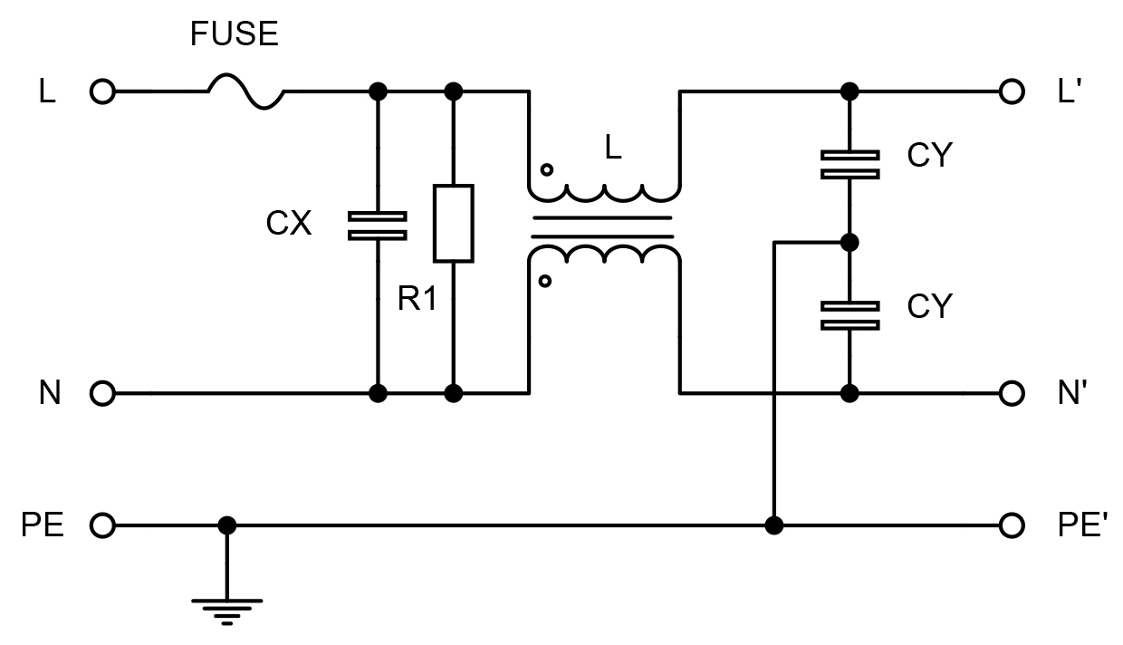
Capacitor CX attenuates differential mode noise, signals and spikes that appear from line to neutral created by rapid changes in current within the converter, and will be rated as X1, X2 or X3 to withstand voltage transients on the AC line. L is a common mode or current compensated choke with two windings phased as shown. Common mode noise, created by rapid changes in voltage within the converter, from line and neutral to ground see the choke as a high impedance with each CY capacitor diverting noise current to ground. Normal running current through the two windings on the choke cause field cancellation in the core so that high inductance values can be used without fear of magnetic saturation. Often, L is wound with less than perfect coupling between the windings so that some leakage inductance is created appearing as a separate series inductance which increases differential mode attenuation.
While CX can be any capacitance value within practical limits, the two CY values are limited by earth leakage current requirements and are available in Y1, Y2, Y3 and Y4 types with decreasing rated operating and transient voltages. Leakage current through the Y capacitors is a potential problem as they bridge a safety barrier – line and neutral to ground. If the protective ground connection to equipment metalwork fails, the casing ‘floats’ up to line voltage through a Y capacitor and could cause an electric shock. Y capacitor values are therefore limited to allow no more than a prescribed current to flow according to the standard used for the application environment. Limits can vary from tens of milliamps in industrial areas down to less than 10µA in cardiac floating healthcare applications.
R1 is a high value resistor, typically 1M ohm to discharge CX if the AC supply is abruptly removed and the load cannot be relied on to drain charge away, leaving a potentially dangerous voltage on the AC connector pins. Standards such as IEC 62368-1 for ITE and media equipment safety dictate that R1 should discharge the capacitor to less than 60V after two seconds for CX>300nF with higher voltages allowed for CX<300nF. For equipment only accessible to trained personnel, again the allowed voltage limits are higher. Other standards are different though – IEC 60601-1 for medical equipment for example, requires discharge to less than 60V after one second but there is no requirement if CX is less than 100nF. Standards such as IEC 62368-1 also put requirements on the resistor to withstand transient voltages with no more than 10% deviation in resistance if the resistor is fitted before a fuse. R1 will therefore be a high specification part. In some applications, the power dissipated in R1 under normal conditions is a limit to compliance with limits for standby or no-load losses specified by bodies such as the US Department of Energy (DoE) and the European ErP directive.
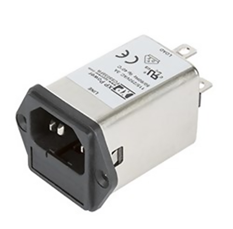
The fuse shown in Figure 1 can be included in modular filters, particularly panel mount types such as the popular IEC320-C14 type (Figure 2).
In commercial applications, a single fuse in the line is normal. If the fuse element is compliant with standards, it eases the specifications of downstream components such as R1 as mentioned. Some applications such as medical devices and class II IT require both line and neutral to be fused to cover the possibility of accidental reversal of the connections which, in a single fuse situation, would leave the live line unfused and reliant on upstream fuses or breakers in the supply opening with a short from live to protective earth . These upstream devices may be rated at a high current value to protect wiring for multiple loads and would not be guaranteed to open quickly for an equipment fault, potentially allowing a fire hazard. Double fusing does have the disadvantage however that a line to neutral over-current could open just the neutral fuse, leaving the equipment apparently dead but still with live connections inside.
Selecting the filter
The mechanical format of the filter is a natural starting point; variants are available as IEC inlets with screw or snap-in mounting with options for a switch and none, one or two fuses according to the application requirement. IEC inlet types are rated to 10A for C14 and 16A for C20 with chassis mount parts available to 20A and higher. Chassis mount filters, which typically have 6-sided shielding along with a direct fixing to conductive grounded metalwork, offer very effective EMI attenuation.
For all types, medical versions are available which omit the Y capacitors, to reduce leakage current to typically 5µA maximum. This necessarily means that common mode attenuation is reduced and may need to be compensated for elsewhere, such as by cascading filters.
Rated current can be easily calculated from the load power requirements given the lowest input voltage, and load power factor. For example, a load on the filter that takes 200W with a power factor of 0.9 at 90VAC would draw a current of 200W/ (0.9 x 90VAC) = 2.47A and in this case, a 3A-rated filter may be chosen.
Choosing the attenuation required from a filter is best done by measuring performance without it fitted, then calculating what extra is needed from an external filter. Attenuation curves in filter data sheets give an indication of performance but bear in mind that the data sheet performance is under specified test conditions, typically 50-ohm source and load impedance. Although the AC source can be standardised with the use of a Line Impedance Stabiliser Network (LISN), the application load is likely to be very different. A filter module cascaded with the internal filter in AC-DC power supplies can also cause unexpected results with potential resonances occurring which can even cause amplification of EMI at critical frequencies. As an example, an EMI plot was taken from a typical AC-DC converter from XP Power, part PBR500PS12B run at 230VAC and 180W shown in Figure 3. The plot shows good compliance with EN 55032 curve B emissions limit line for quasi-peak detection. A filter was then inserted in the AC line, type XP-Power FCSS06SFR, with the attenuation characteristics as shown in Figure 4. The dotted line is differential mode and the solid line common mode attenuation. The resulting overall result is given in Figure 5.
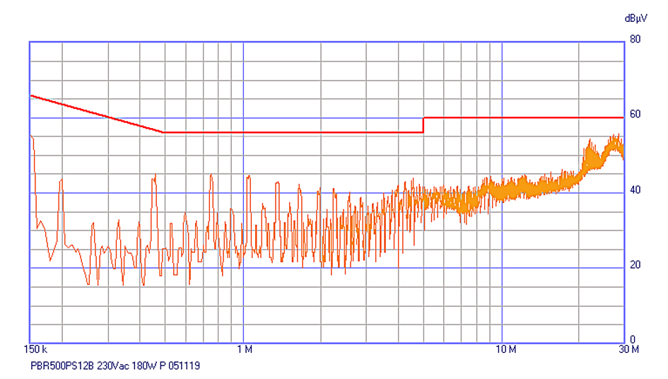
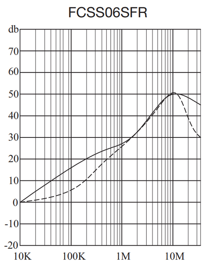
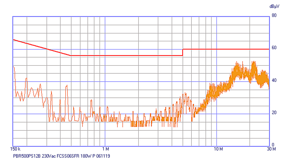
It can be seen that up to around 1MHz, the filter attenuation drops emissions by the expected amount but at 10MHz and above, the improvement is not in line, signifying that the modular filter is not ‘seeing’ 50 ohms as a termination at these frequencies and giving lower attenuation than might be expected. This confirms the necessity to make practical measurements to confirm compliance.
Consulting the experts
Getting EMC compliance right at the earliest stage is vital to avoid costly failures at final product testing. The solution is not just an oversized modular filter at the AC inlet which can add unnecessary costs and even be counterproductive, with unexpected attenuation results. Power supply manufacturers can help and have complemented their range of AC-DC power supply products with modular filters with current ratings from 1 to 20A in chassis mount and IEC inlet formats. Versions are available for ITE, industrial and low-leakage medical applications with more to be added including filters for high current three-phase applications.
By Gary Bocock Technical Director, XP Power