


Wireless connectivity . in cars is becoming more and more important. The functionality of the cars depends on a reliable wireless communication, e.g., for safety systems, infotainment, traffic warnings and updates of software and maps. To ensure that the desired and required wireless communication is achieved, extensive testing needs to be performed. Today a lot of the testing is done with drive-tests out in the field. However, this is both expensive and can only be done late in the development process, which makes it hard to modify the product.
Another problem with field-testing is that they are not repeatable, since the environment changes between measurements. This makes it difficult to identify the reason behind the changes in the results. Thus, exists the need to perform the testing in an earlier stage in the development, but also in a repeatable manner. No standardized method of how to do the testing of the wireless communication for vehicles exists today. Instead, wireless communication testing has been extensively investigated and developed in the mobile phone area. Different methods to perform mobile phone testing are, for example, the Multiprobe Anechoic Chamber (MPAC), the two-stage method and the Reverberation Chamber (RC).
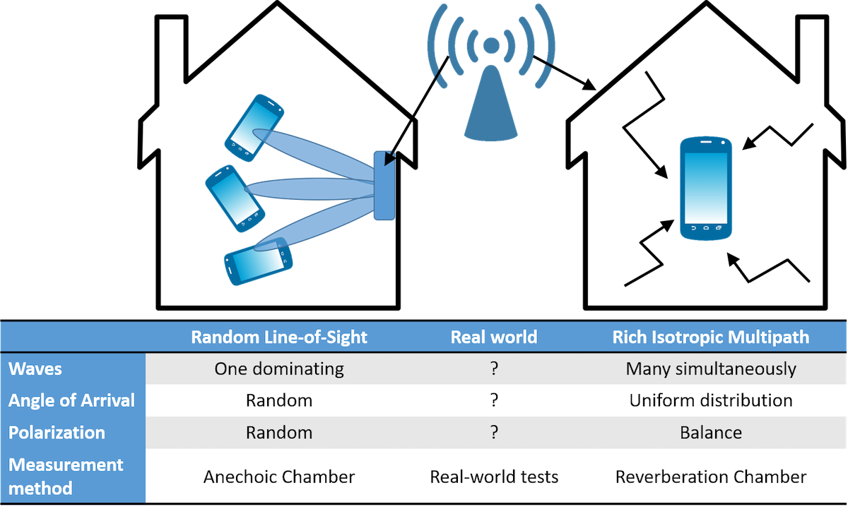
However, it is not problem-free to adopt these methods for vehicle testing. There are issues with the size of the test object, as well as a different propagation environment for cars as compared to mobile phones. In [1], a hypothesis states that, “If a wireless device is tested with good performance in both pure-LOS and RIMP environments, it will also perform well in real-life environments and situations, in a statistical sense”. This hypothesis introduces two edge environments, i.e., the Rich Isotropic Multipath (RIMP) and the Random Line-of-Sight (Random-LOS). These environments can be seen as each other’s opposites, where the RIMP environment is based on an environment with many incoming signals, whereas in Random-LOS environment there is only one dominant random signal. Real-life propagation channels will lie in between these two channels.
Real-world Hypothesis
There is no easy way to evaluate the performance of different user devices in all possible, or even in most typical, environments. Ideally, it would be desirable to make sure that the device works well in all real-world environments in which it will be used in, but this is not feasible. However, in practice, typical channel models are used to emulate different real-world scenarios. The hypothesis presented above is yet to be proven, but it provides an appealing and practical framework within which many devices could be evaluated in a cost and time efficient way. The two edge environments, RIMP and Random-LOS are presented more in detail in the following sections and in Fig. 1.
Rich Isotropic Multipath (RIMP)
The Rich Isotropic Multipath (RIMP) environment is an ideal fading environment, that does not exist in reality, but that has been proven to be very useful. The first word, Rich, refers to that there are many incoming waves simultaneously. Isotropic refers to that the Angle of Arrival (AoA) of the incoming waves are uniformly distributed over the unit sphere, which means that the orientation of the DUT will not matter. The last word multipath refers to that the waves have taken multiple paths to the receiver. The RIMP environment can be emulated in a reverberation chamber. Real multipath environments are seldom isotropic like assumed in RIMP; however, if we consider a larger period of time and a number of mobile phone users, then the environment will be approximately so. The reason is that mobile devices can be used in different orientations, e.g., in talk mode and surf-mode, and they are located in different locations in respect to a base station.
Random Line-of-Sight (Random-LOS)
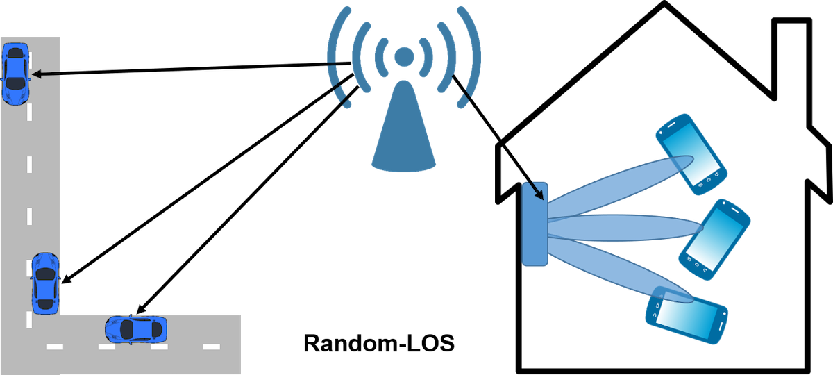
The Random Line-of-Sight (Random-LOS) environment consists of a dominating incoming wave, which most of the time is a LOS contribution, but it can also be a strong diffracted or scattered wave. The difference with the traditional LOS environment is that at least one of either the transmitter or receiver is randomly oriented. Usually it is the user device that is randomly oriented, since the base station normally is placed in a fix position. By introducing an ensemble of users over time, the statistics of the DUT orientation will become increasingly random, and thereby the randomness in the LOS component will increase. The randomness in Random-LOS refers both to random AoA and random polarization. When a DUT is randomly oriented in a 3D environment, both the polarization (considering linear polarization) and the AoA of the incoming wave will change relative to the DUT. Different user devices will experience either a 2D or a 3D Random-LOS, see Fig. 2.
For example, a small handset (i.e., a mobile phone or tablet) can be oriented in any direction in space, since people are using them in talk-mode, surf-mode, etc. Vehicles, on the other hand, will only be oriented randomly in the horizontal plane with some slight elevation angles. This corresponds to a 2D random AoA and one dominating polarization.
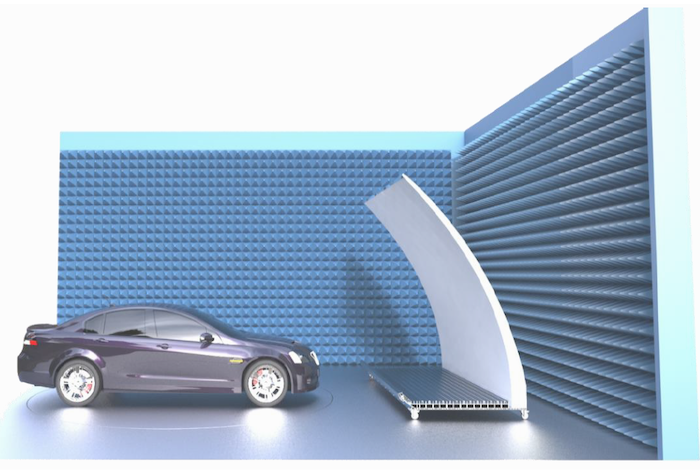
An idea for realizing a 2D Random-LOS test environment for testing the wireless communication performance of vehicles was presented in [2]. The 2D Random-LOS is a relevant environment for vehicles, since vehicles often are used on highways and in rural areas where there is often a LOS component to the base station. To emulate a base station in Random-LOS, it is needed to perform measurements emulating the far-field region of the base station. By generating a plane wave, the far-field can be emulated. A plane wave can be realized with a reflector with a linear array feed, similar to a compact range, see Fig. 3.
The feed of the reflector consists of a linear array feed of dual-polarized antenna elements. The antenna elements in the array are combined using a beamforming network, where the combination is done separately for each polarization. This results in two ports, i.e., one for each polarization. By connecting a communication tester to the ports, a base station in far-away LOS can be realized. When the vehicle is rotated on a turntable, the performance can be evaluated for different rotation angles or different AoAs. In this way, the 2D Random-LOS environment can be realized for testing the system performance of vehicular wireless communication. The reflector solution is modular and can easily be made wider by extending the linear array feed and adding an extra piece to the reflector. The reflector in Fig. 3 has a height of 3 m, a width of 4m and a depth of 1.5 m.
Measurement examples
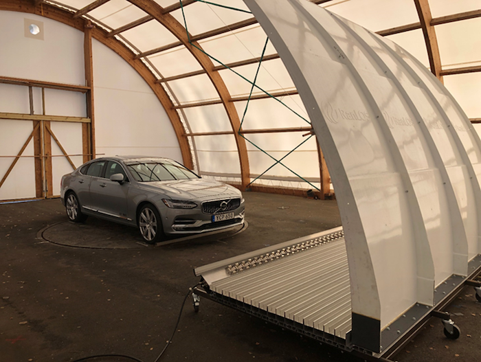
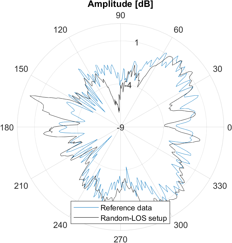
The Random-LOS measurement setup was mounted in an outdoor open area test site covered by a large tent, see Fig. 4. By connecting one port of a network analyzer to the reflector antenna system and the other to an antenna on the vehicle, the radiation pattern of the vehicle antenna, including the effects of the vehicle itself, can be measured simply by rotating the vehicle using a turn table. As an example, this was done for a roof mounted sharkfin antenna on a Volvo S90. The measurements can be done very quickly, it takes only as long time it takes to rotate the turn table a full revolution. In our case it took about ten minutes to measure the radiation pattern for a full frequency sweep. The measurements were compared to measurements done in a traditional antenna measurement facility using near-field samples which are converted into far-field radiation pattern using a mathematical transformation. Such measurements require accurate positioning of the measurement probe and many sampling points, thus taking much longer time. The comparison is shown in Fig. 5. It can be seen that good results can be achieved using the Random-LOS measurement setup.
Acknowledgements
The project is partly supported by the Swedish Research Council VR, through an industrial PhD project and partly by the Swedish Governmental Agency for Innovation Systems (VINNOVA) within the FFI project SIVERT.
Much of the information presented in this article comes from [3].
Madeleine Schilliger Kildal, RanLOS AB and Industrial PhD student at Chalmers Lars Granbom, CEO RanLOS AB Jan Carlsson, Provinn AB and adjunct professor at Chalmers (supervisor of Madeleine)
References
[1] P.-S. Kildal and J. Carlsson, ‘New approach to OTA testing: RIMP and pure-LOS reference environments and a hypothesis’, in 2013 7th European Conference on Antennas and Propagation (EuCAP), 2013, pp. 315–318.
[2] P.-S. Kildal, A. A. Glazunov, J. Carlsson, and A. Majidzadeh, ‘Cost-effective measurement setups for testing wireless communication to vehicles in reverberation chambers and anechoic chambers’, in 2014 Conference on Antenna Measurements Applications (CAMA), 2014, pp. 1–4.
[3] M. S. Kildal, ‘Evaluation of the Random-LOS Measurement System for Vehicular Communication Applications’, Licentiate thesis, Chalmers University of Technology, Gothenburg, Sweden, 2017.