


The use of . solar panel systems is rapidly increasing and some of these systems are co-located in the vicinity of wireless systems. Measurements have shown that the radiated emission from solar panel electronics can reach considerable levels, in some cases even above CISPR 22 Class B. Here, examples of interference impact is discussed for two examples of wireless applications, air traffic control communications (ATCC) and High-Frequency (HF) communications. The overall conclusion is that co-location of solar panel systems with wireless communications, must be carefully analyzed not to create interference problems.
.
Background
In recent years, solar energy systems have become more and more widely used. The interference issues associated to these systems have also started to gain interest, since both conducted and radiated electromagnetic emissions are generated by such systems [1][2][3]. Several studies have been performed in order to investigate the levels of conducted and radiated interference from solar panel systems. The EMC Administrative Co-Operation Working Group has published the results from the 6thEMC Market Surveillance Campaign 2014 [3] [4]. Among the conclusions, the report states that the results of the technical assessment of solar panel inverters showed that approximately a third of 54 EUT (Equipment Under Test) tested were compliant (33% overall compliance) with EN 55011. Other measurements have shown radiated emission levels that equal CISPR 22, Class B (40 dBμV/m, at 3 meters distance) [1] over the whole frequency range 30 MHz – 200 MHz.
Other measurements show field levels of 10-15 dBμV/m for the same frequency range at 3 meters distance [2][8]. In [5], radiated emission levels in the order of 50-60 dBμV/m for 1 kHz resolution bandwidth, were measured in the HF band. The results are importantfrom an EMC point of view, since several wireless services use these frequency bands.
Solar panel systems and EMC testing
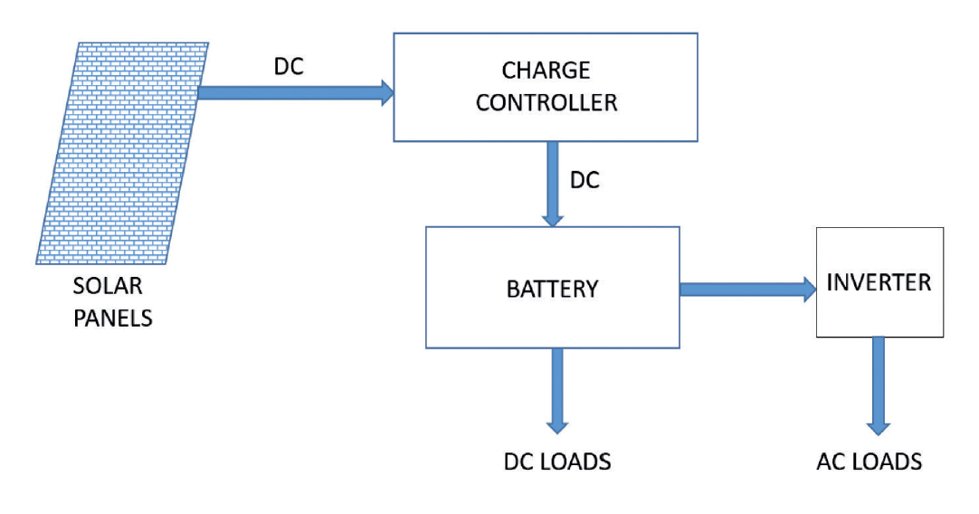
A simple schematic overview of an example on a solar-inverter system is shown in Figure 1. The solar panels consist of photovoltaic converters that produce DC into the charge controller that feeds the battery pack. From the battery pack, the DC power is converted to AC for usage, either directly or via a connection to the power grid. The sources of electromagnetic interference from solar systems are typically grid-connected photovoltaic (PV) inverters and optimisers. Off-Grid inverters convert DC power stored in batteries to AC power. Off-Grid inverters typically deliver one of three output waveforms; square wave, modified square wave or sine wave. Grid-tied inverters convert the DC power output of a PV generator to AC power for the utility grid. Hence, they must deliver a pure sine wave, in-phase with the grid [1].
A power system with this type of inverter uses the grid as a storage battery. Hybrid inverters can operate both as an Off-Grid inverter and as a Grid-Tied inverter at the same time. Solar panels have limitations concerning the speed at which the cell can convert solar photons into electrons, ambient temperature, and other issues. There is a complex non-linear relationship between voltage, current and the total amount of power produced. In order to optimize collection, several modern systems therefore use power optimizers. The power optimizer increase the energy output from the PV systems by constantly tracking the maximum power point (MPPT) of each module individually. The total output of the array is monitored and a continuous adjustment to the presented load is performed to keep the system operating at its peak efficiency point. The optimizers are often located close to the individual solar modules and can be a source of interference [6].
At present, there are no EMC standards specifically dedicated for regulating solar inverters [9]. At various times, solar inverters have been defined as household appliances; ISM (industrial, scientific, medical) equipment; or as information technology components. These arbitrary descriptions would make solar inverters subject to EN 55014, EN 55011, or EN 55022. Other examples are the generic standards EN 61000-6-3 and EN 61000-6-4. A basic challenge in EMC testing of solar inverter systems is that during testing, cable lengths in the order of a few meters are used. In the practical application, however, considerably longer cable lengths could be the case e.g. lengths in the order of tenths or hundreds of meters [1]. This difference in cable lengths can lead to considerably higher levels of radiated emission, since the cable’s antenna properties could be significantly changed compared to testing.
Interference impact from solar panel systems
One consequence for wireless communications, subjected to electromagnetic interference, is reduced communication range before any interruption occurs. If a wireless receiver is subjected to interference from co-located equipment, the noise level in the receiver will increase and in turn reduce the communication range for others to reach the receiver. The problem in this case is that the operator, close to the interference source, may not recognize that an interference problem has occurred. This is the case as long as the communication distance is within the reduced range so that interruption has not yet occurred. Furthermore, this increase in noise level will also reduce the margin against other potential interference problems in an uncontrolled manner. Such a situation is a serious problem in safety & security applications if a certain specified maximum communication distance is necessary to achieve for an application.
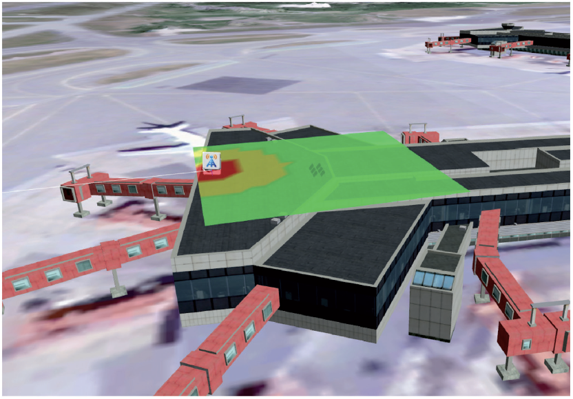
In Figs 2 and 3, examples of interference impact from solar panel systems on wireless communications are showed. The calculations are done with the tool GENESIS [7], developed by the Swedish Defence Research Agency (FOI) with financing from the Swedish Defence Materiel Administration (FMV). In Figure 2, a radio receiver for air-traffic control communications at 118 MHz is co-located with a solar panel system that radiates according to EN 55022, Class B. The risk area around the receiver is colored with green, yellow and red color, depending on the interference impact on the receiver. These colors corresponds to the interference-risk levels Low, Medium and High respectively.
In this scenario, the performance of the wireless system will start to decrease at co-location distances in the order of 20 meters if the interference signal is dominated by CW (continuous wave) that equals the level for EN 55022, Class B. One consequence for wireless communications, subjected to electromagnetic interference, is reduced communication range before any interruption occurs. If a wireless receiveris subjected to interference from co-located equipment, the noise level in the receiver will increase and in turn reduce the communication range for others to reach the receiver. The problem in this case is that the operator, close to the interference source, may not recognize that an interference problem has occurred. This is the case as long as the communication distance is within the reduced range so that interruption has not yet occurred. Furthermore, this increase in noise level will also reduce the margin against other potential interference problems in an uncontrolled manner.
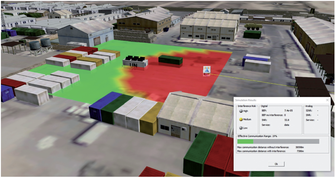
In Figure 3, an example of an analysis of reduced communication range is shown. The communication link uses a High-Frequency (HF) ground wave communication link of 8 km, working at 3,77 MHz and with an output power of 50 W. It is co-located with a solar panel system at 20 meters distance. The interference level is measured to 60 dBμV/m at a distance of 1 meter from the solar panel system. In this case the interference from the solar-panel system reduces the communication range to about 19% of the maximum possible range. Thus, in this example the electromagnetic interference reduces the communication range significantly.
Conclusion
The overall conclusion is that co-location of solar panel systems with wireless communications, must be carefully analyzed not to create interference problems.
Peter Stenumgaard, Sara Linder Swedish Defence Research Agency (FOI)
References
[1] H. J. Loschi, L. A. S. Ferreira, D. A. Nascimento, P. E. R. Cardoso, S. R. M. Carvalho, and F. D. Conte, ” EMC Evaluation of Off-Grid and Grid-Tied Photovoltaic Systems for the Brazilian Scenario”, Journal of Clean Energy Technologies, Vol. 6, No. 2, March 2018.
[2] Juswardy, B.; Schlagenhaufer, F.; Padhi, S.; et al., “Title: Radiated EMI emission study on photovoltaic module for radio astronomy receiver front-end”, Electromagnetic Compatibility Symposium (EMCSA) 2011, Perth, pp. 1-4, 9-11 Nov. 2011
[3] EMC administrative co-operation working group, “Report on the 6thJoint Cross-Border EMC Market Surveillance Campaign”, 2014
[4] EMC administrative co-operation working group code of practice on the 6thJoint Cross-Border EMC Market Surveillance Campaign, 2014
[5] Henrik Olsson, “EMC-mätningar Solcellsanläggning Glava Energy Center”, Elsäkerhetsverket doc no. 16EV1277, 2016-12-02.
[6] T. Brock-Fisher, ”Can Home Solar Power and Ham Radio Coexist?” Qst, pp. 33-37, 2016. Available: https://search.proquest.com/docview/1783658671?accountid=28067
[7] P. Stenumgaard, L. Junholm, and K Wiklundh, “GENESIS— A Software-Based Research
Platform for Intersystem-Interference Analyses on e.g. Camps,” Proc. NATO Military Commun. and Info. Sys. Conf., Prague, Czech Republic, Sept. 29–30, 2009.
[8] EMC Test Report for solar inverter model HiNRG1G03EU(SE), Els.kerhetsverket doc. no. 14EV1597_252992-21E, 2014.
[9 Siegfried W. Best, “EMC regulation of solar installation equipment has failed to keep pace with actual developments”, Interference Technology, Item Media, July 18, 2008.