

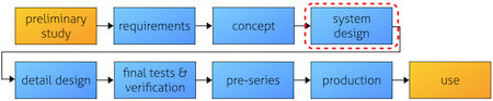
System EMC Design . This article is a part of a series of texts that will deal with the EMC challenge in terms of project management and the practical EMC activities at different stages in the project flow. Different companies all have their own way of describing their project flow, so to keep it simple we will use the labels as given in Figure 1. We can call it a generic project flow. The picture only describes the basic outline of the work packages. These articles will describe the actual practical work we want to do in the project to “make EMC work” in a time- and cost-efficient way. Each part of our series will fill in the details for each part piece by piece.
This is the fourth part – System EMC design – in our process picture . We have previously looked at the EM environment, requirements and possible disturbance risks. We will here prepare our defense – building a fortress for our electronics. We will build A Great Big Wall (in a positive sense)!
The content of system EMC design
System EMC design can be applied on all scales on a design – from nation-scale networks, industrial buildings and down to cabinet installations and sub-racks. We could also picture ourselves dealing with partitioning of functionalities between different PCBs or even sub-sections of a PCB. My example here is put in the mid-range as a sort of compromise: cabinet and rack installation of systems containing different kinds of PCBs and sensors.
We now describe the system in more detail. The situation is now better described compared to the concept stage, and we have now settled for a set of included parts. Using the EMC zone description, we decide on how to design our protection. When we look at this map, as shown in Figure 2, we use our experience and EMC design guidelines. The critical points in the design are pointed out, which gives us a focus for the future work.
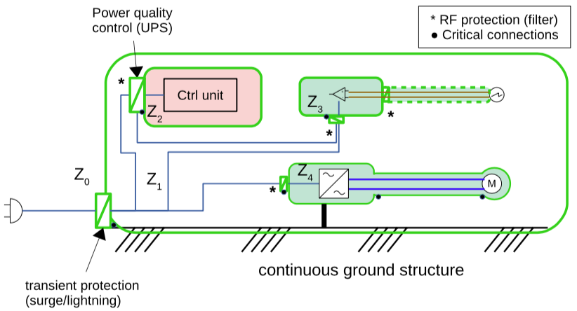
We now have a basis for the EMI risk analysis, as described later on. It is important to cover all optional configurations of the system, so we do not get a surprise and are left with components/installations not covered by our protection, e.g. an additional unprotected signal cable coming in from another system (being installed God knows where). In the system description, we can provide a list of protection choices made: shielding, filtering, isolation vs grounding.
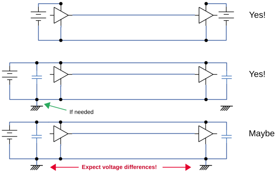
On the system level, it is important to state who is making a ground connection in which component, and why. With a structured grounding (and isolation) scheme, we reduce the risk of having unnecessary circulating currents. This is often called ground loops, but it is not a loop in the ground that is the problem. The actual risk is that we may connect our system at two points of the external ground structure (such as widely separated building parts), and we can not guarantee that we have zero volts between these points – especially at radio frequencies.
EMI risk identification
We now have a better view of the actual physical design of the system. Specific design risks, such as shielding leakage, assembly, material problems can now be evaluated. This analysis will give you more insight into where the largest risks lie in the design, and you can then update the Compliance check list with new design testing. An example of such a risk assessment is shown in Figure 4. With the help from our previous analyses (environment review, EMI risk analysis and zoning) in combination with our experience from previous projects we can make an improved assessment of the primary risks – since we now know more about the components. We find that the Control unit contain a display and a keyboard, which will be exposed to a high ESD threat.
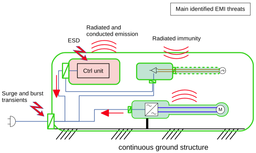
From experience, radiated and conducted emission is also critical to check. The switched mode power drive is always prone to emit fields and currents (as we remember from the previous project mishap). The sensor system, on the other hand, needs to be checked concerning immunity. From this picture, we can generate a list of priority design tests dedicated to each sub-system. By doing this, we can focus our energy on critical EMC design work (but without forgetting the other risks, they are not zero-risks). With dedicated design testing for each unit, we get valuable feedback early in the process. Regarding surge threats, we find – by using the zone map – that such testing is best performed on system level.
By eliminating risks using a cunning system design, you will also reduce the amount of testing – since testing shall reflect the actual risks. You will also save money on the amount of protective devices. In our specific case, we will concentrate transient protection to one single inlet rather than having multiple power feeding points.
EMC design reviews
At this stage, we can now start with the first EMC design reviews. These are based on the EMC Zone description and the EMI risk analysis. The reviews shall result in a set of instructions for both system and detail design – as an input to the respective designers. A proposal is to generate an EMC design check matrix (as we have discussed before) where we enter the critical items that need our specific attention. The list could contain both specific needs for particular protective components as well as general requirements on e.g. surface treatment of shielding enclosures. The list can also include references to what type of EMI risk we are dealing with to make it more connected to why we are doing this.
Installation preconditions
On system level, much improvement can be obtained by applying requirements on the physical installation of components and cables. Some companies use specific Installation Control Documents – ICD – for keeping track of this, including several aspects such as mechanical stability, electrical safety, as well as EMC. Such instructions may include
- ground structure quality
- grounding instructions
- isolation instructions (e.g. for sensors)
- cable routing (distance from ground plane, length restrictions, separation of cable classes)
The EMC test plan
Test Planning is an efficient tool for guiding your design efforts. Specify how the test shall be carried out in detail. Then the designer knows what to protect against (and also what is not necessary to work with), and how the software should support the testing.
In order to get a good quality of the EMC test, it is extremely important to make a good test planning. The handling of this activity varies widely depending on the industry. In the automotive industry, most of the vehicle manufacturers have a strict handling of test planning. The test plan that the subcontractor writes must have been approved by the car manufacturer in good time before testing is permitted to be carried out. It is therefore forbidden to perform EMC testing without a test plan, and this often results in well-deserved results in testing quality and reduced set-up problems. There are similar arrangements in the military and telecom industry. In other industries, such as industrial electronics if we look at a common application, the routines vary greatly. It could range from
- getting a finished document with well specified setup descriptions well in advance to testing
- to the situation that the EMC lab calls the customer a few days before testing, asking how they want to perform the test and what equipment they will bring along
To get the full value of an EMC test, it is critical to make a good test plan!
This document should also not be written in panic a few days before a test, but one should start with it as soon as one has determined the requirements (which one should also do early and not the week before the test) and the system concept is defined. Included in this work are among other things.
- What requirements must be met
- The interpretation of how the requirements should be verified for the product in question, e.g. which interfaces with cables to be tested and with which methods
- Definition of performance criteria to be monitored, and which parameters should be monitored to detect errors. This is a very important point, which gives the basis for how to carry out the testing and how the software should support this. You should find the input for this work from the Requirement Analysis (article 2 in this series).
It is important to consider the following aspects carefully:
- Which accessories to use
- Which cables to use: type, lengths, connectors – adapted to the actual tests to be performed. They will not have the same length as in the installation, but will have to match the laboratory interfaces
- Test connections: some interfaces are only used for evaluating or stimulating the test object. These connections shall not influence the test result (can be both disturbing and protecting!), so they need special care
- What operating modes the product should run in and during which test cases. By making a rational selection you reduce test time as well as (possibly) increase the test quality
- Which test software to use as interface to the test object. You will most likely need to have some tailoring made to be able to monitor details of interest (e.g. amount of error frames) and many times also the speed of testing.
In principle, you might say that a test plan is a test report before entering the results. The additional effect will thus be that the test report also becomes better.
There is often a confusion about what the content of these plans really is. Many larger companies therefore distinguish between the following:
- EMC test plan: an Excel spreadsheet stating what tests that shall be made, but without any details. We propose to replace this with the EMC Compliance matrix.
- EMC Verification Plan: a detailed description of how testing is planned to be performed in the EMC lab
Improving testing quality: Early wish lists
By creating the EMC verification plan as we have described, we now have the ability to create a wish list. This list will contain a set of requests, so that we during testing will be able to monitor pass/fail.
To the hardware designer:
- Additional signal interfaces, only intended for monitoring and control of the Equipment Under Test (EUT)
- list of Auxiliary Equipment (AE) that is needed for providing full function for the EUT. In the vehicle industry, by tradition this AE is called Load Box.
- Load simulation for those interfaces where we can have simplified replacements (resistors etc) for the actual sensors etc. that the test object will connect to. For vehicle component testing, this is often a part of the Load Box.
To the software designer
- A list of wanted signal and data monitoring that is readily available
- An effective summation of the EUT status, simplifying the status check
- The possibility to turn on and off different functions, both for switching operating modes and for troubleshooting
- If necessary, trimming of the EUT activity to speed up or simplify testing
Document structure
Where is the map? Again, this is a critical issue: to have control of the EMC Zone concept. In addition, we now want to have a tracing to the system design status since it will most likely develop and change over time.
What other documents do I store? Try not to invent new documents if you can find existing structures to place the information into. Just make sure that there is an EMC responsible person that keeps track of the updates on the EMC relevant part. How to split up documents so they will fit your design process is up to you.
Input and Output
As a summary, we find the following interface conditions to the other parts of the project flow.
Input from previous work:
- System concept design
- Zone description
- Requirement specification
- Installation preconditions
- Best practice EMC design – design rules
Output from this stage:
- Updated EMC zone description – with implementation
- Updated EMC design check matrix
- – From the EMC design reviews
- Allocation of requirements to components, both for Hardware and Software
- Compliance matrix
- – updated with specific tests
- – Including dedicated pre-tests
- EMC verification plan, based on Compliance matrix
Closing remark
The way I describe the activities here may seem rigid and somewhat square – and that is made on purpose. A template for workflow is always a simplification. In reality, risk analysis, zoning and system design are interacting tasks. The important thing is to have a clear view of the wanted output: a robust platform design created from known preconditions. From this point on, the zone description and the EMC verification plan are two of the critical guides for the final success: pass at the EMC testing.
Lennart Hasselgren, Lic Eng.
EMC Services, lennart@emcservices.se If you have ideas and comments on this article, please feel free to mail me! Some might also recognize my short examples, and if you want to add something that would be an interesting talk.