

What is the electromagnetic environment? The EMC part of the prestudy .
This article is a part of a series of texts that will deal with the EMC challenge in terms of project management and the practical EMC activities at different stages in the project flow.
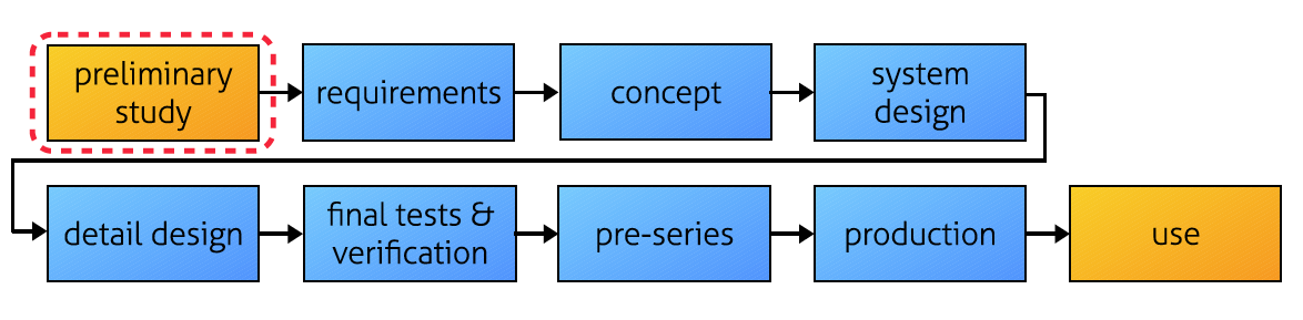
Different companies all have their own way of describing their project flow, so to keep it simple we will use the labels as given in Figure 1. We can call it a generic project flow. The picture only describes the basic outline of the work packages. We will not involve ourselves in various management buzz words or state-of-the-art management designations. These articles will describe the actual practical work we want to do in the project to “make EMC work”in a time- and cost-efficient way. Each part of our series will fill in the details for each part piece by piece.
Why bother?
I have experienced many development projects, where EMC has been regarded as a ghost that someone else should take care of. The “mission impossible”is held at a distance, and there are many other priorities to cling on to. That type of response in these cases may be based on different attitudes such as:
- EMC is a testing issue, so we wait with that work until we get to the lab. Basically, we just need a test report from the lab before we start to sell it.
- Yes, EMC is important to deal with –but we do not really know what to do about it. But we do have a metallic enclosure, and there are some filters. There are a lot of other things to do, and EMC feels complicated and fuzzy, so we deal with that later on and hope for the best.
But there are also many engineers who take EMC very seriously, and they have better progress and a faster pace in their projects. Hopefully, such readers may also find some new hints on how to speed up their work by reading this article series. My mission here, is to say that waiting with the problems will not make them smaller.
Planning ahead for EMC will save you time and money!
In order to do that, we must handle EMC as an integrated part of the product development process. Do not treat EMC as something that you can handle with a cheap quick-fix in the lab. It will not be quick, and it may not be cheap (at least there will be some re-testing). On the other hand, we do not want to create a parallel unique process for EMC – making it exotic and seemingly costly. In the same way as you check that your power supply will provide the correct voltage, cope with temperature, fit within the enclosure etc –you also check the EMI risks with the design. The important thing is that you have a map to follow, otherwise you might be lost in the wilderness. Keep it simple –but with complete coverage.
The starting point
When a new product is to be developed, the primary question is: who is going to buy it – and why? For the EMC issue, the answer to these questions will result in:
- There will be a user, who will operate the product in some way which will expose the equipment to an electromagnetic environment. The installation may induce new risks that were not considered before.
- Depending on location, there will be different types of disturbances
- The user will have other nearby equipment which will set your limits in real life. Are they very sensitive?
- If there are multiple user scenarios, you will have to find out your worst case
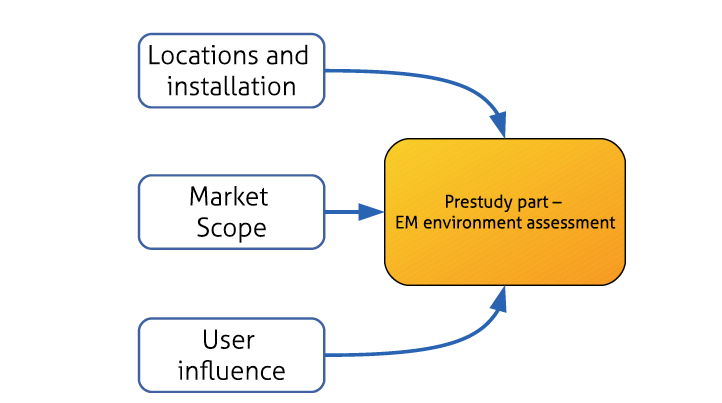
To find the information you need, you will have to look at the end use of the project. One way is to talk to your market department about the scope of the product. They do not need to know details about EMC. Using your imagination and your own product experience, you can have a dialogue about typical – and also special! – user scenarios in terms of cable lengths, adjacent systems, operator actions etc, see Figure 2. Another way is to join visits to customers and look with your own eyes, this time with your EMC goggles on.
Examples of environments
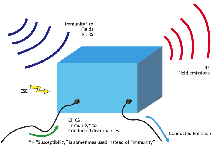
In a general sense, we can distinguish between some basic types of environments due to the inherent use of equipment that they are linked to. A list is presented in List 1. By looking at this list, we can understand that CE-marking is not related to a fix test level. The requirements vary with the environment, just as durability to vibration does. Normally, you can find EMC standards that correspond to these environments but be aware that the requirements may not be complete. In parallel, you need to look at the real world scenarios and group them into phenomena as given in Figure 4:
- How low emission is required due to the neighbor systems, directly from the enclosure and indirectly via the cables
- How large field strengths may the product be exposed to, onto the enclosure and via the cables
- How large transients may I expect coming in on the cables, and from what
- How large is the risk for static charge build up –causing ESD
List 1. Examples of environments
• Residental, commercial and light-industrial
– usually less threat of interference.
• Industrial
– higher requirements for interference immunity.
• Marine
– specific radio communication, possibly requirements of classification.
• Automotive
– specific power quality, high company requirements.
• Controlled lab environment
– requires protected installation.
• Switchgear
– significant transients.
• Railroad
– significant transients, strong magnetic fields.
• Other requirements, such as security, intrusion detection, and cost of errors can effect.
Different environments mean different requirements in the standards.
Different levels of investigations
The assessment of the EM environment may be performed with different amount of effort, depending on the need. For example, we can carry out a detailed measurement at a specific site. Figure 5 shows such a case, where we made a detailed measurement of the electromagnetic environment in the MC2 laboratory at Chalmers University (CTH). There would be new sensitive instruments installed, and CTH wanted to make sure that there would be no large disturbances that e.g. might cause faulty registrations. Just imagine, that your Ph.D. thesis would be based on irrelevant mobile phone exposure…
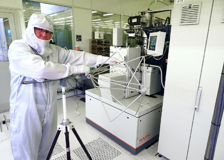
In fact, the supplier of the new instrumentation actually requires that the lab maintains a sufficiently low magnetic field ambient at low frequencies. Otherwise –no instrument provided! That is indeed a high quality profile for a manufacturer. But Chalmers wanted to go one further step and also check the RF ambient in the laboratory, and that is the situation shown in the picture. When you perform such a measurement, you must make sure that the configuration and operation of all systems in the installation are relevant –also on the other side of the transparent wall! The result of these measurements showed, that there were no field generation that could jeopardize the research – so work could continue. But let us say that MC2 finds some new equipment in the future that will work at RF frequencies at higher sensitivity? Then they will now have a reference material as backup for the new situation. The need for EM environment is constantly evolving.
If you need to know more about your product´s EM environment, you can make detailed measurements at dedicated sites that are hand picked to show interesting data. Another way is – as is sometimes performed by the vehicle industry – to attach registration instruments to your product as it moves around. The nice part of such a study is that you get a lot of detailed data on the every day normal exposure for the product, including variations. The drawback may be –unless you specifically know where to look – is that it is hard to find your worst case.
As an alternative, you can do a theoretical study. Some years ago, we performed such a study for a vehicle manufacturer where we looked on the market for different types of radio transmitters that could be found both on the inside (portables of different kinds) and the outside (stationary transmitters) of the vehicle. These data were then combined with assumed user scenarios that generated the distance to the antenna etc, and then the risk levels could be calculated. The study was then expanded to cover other aspects as well.
Another way is to look for existing published standards – surfing the CENELEC site for instance. But be aware that the standards are often political compromises. They tell you what the committee has agreed on, not necessarily the worst case that you are looking for.
User scenarios
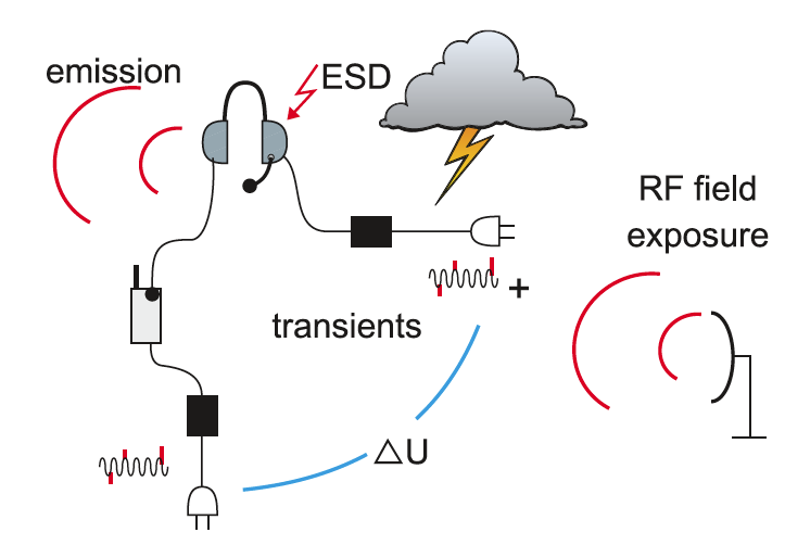
The way the users operate your product is often also a large factor that influences the EM exposure for your equipment. It is a good practice to ask the customers what they really do with your products. Most users are happy to tell you what they do, so the challenge is to find the interesting reference users. A variant of a complex user situation is shown in Figure 6, with a headset as example. From a product point of view, there is only a power and audio plug with short cables so they are seemingly no big pickups for external disturbances. But, since they are used together with other adjacent equipment, transients and fields may be picked up by the system as a whole and possibly ending up in your component. So, power transients may still be a problem for the headset.
One way can be to talk to your maintenance personnel, since they have met several customers and can make a selection – or even just show you what they do. I participated once in such an exercise. Asking his maintenance personnel, the engineer got a bit pale in the face when he realized that by the way things were operated, there would be a generation of large potentials between critical parts in his equipment. The risk of damages was imminent. Was there a link to the high warranty claims? Probably yes…
Who are your neighbors? Some years ago, I saw a drastic example in a workshop presentation. Traditionally, electrical power transmission systems are placed on ground having a good clearance to the surroundings. Now, there would also be an offshore installation. Naturally, corrosion and waves (of water) were of high interest. But then it was also discovered that there would be helicopters landing on top of the installation. Whoops, we suddenly got an avionic environment on our hands with critical and sensitive radio transmissions. A new assessment had to be made, presumably some measurements on existing installations and then a plan for handling the situation.
How to document
After we have completed all this work, having some data, some paper notes, and some interesting personal thoughts –what do we do with the information?
There is a high risk of just putting the information somewhere, where it will be forgotten. But one of the main goals with these studies is to convert the information into the selected requirements. So, this is an input to the requirement allocation –next part of the article series. That means that we skip ahead a bit in the series and talk about the requirements-to-be. Where did these requirements come from? What assessments did we do? And, not to forget: what risks did we not include, since they were regarded as too low, too exotic or too costly?
The last question is of high interest for the future. The assessments made were relevant at the time, but the EM environment is constantly evolving. Regular updates are essential, which means that traceability will also save you money.
Lennart Hasselgren, Lic Eng.
EMC Services, lennart@emcservices.se If you have ideas and comments on this article, please feel free to mail me! Some might also recognize my short examples, and if you want to add something that would be an interesting talk.