


One of the most important . measures to achieve good EMC characteristics is to bond all metallic (conducting) structures together with many wide connections. Connect metal to metal by as large area as possible, with good surface conductivity. These joined parts form a conductive equipotential structure, that act as a reference plane or ground for all electrical and electronic circuit in its vicinity. In practice, the apparatus body and the metal casing, forms this reference plane. In most cases, the ground planes in PCBs must also be connected to the reference plane to achieve the desired EMC properties.
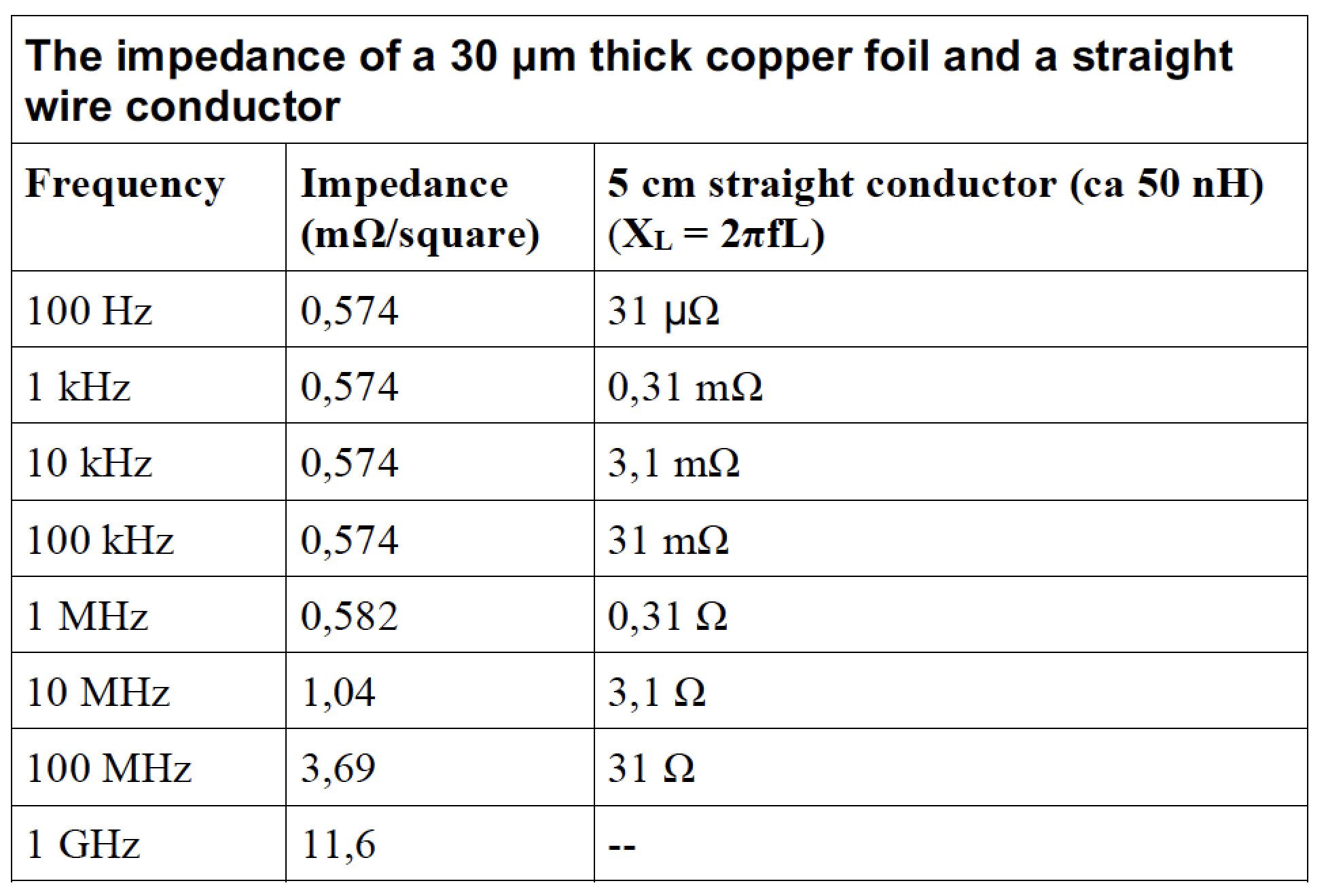
Impedance (Z) is the resistance (= the opposite of conductivity) of electrically conductive material for AC. At DC and low frequency AC currents, the impedance is dominated by the resistance (r) according to the formula Z = r + jωL. With increasing frequency the inductance (L) becomes the dominant part of the connection. A rule of thumb says that a copper wire represents an inductance of 1 nH / mm (= 1 µH / m). As we discussed in the previous article on cable shielding, wire connections, so-called ”pigtails” in most cases, are not good enough to connect the cable shield to the apparatus shield. Table 1 shows the impedance at different frequencies of a copper plane compared to a straight copper conductor.
All electrical activity (digital or AC) going on in electric or electronic circuits and conductors generate unintentional electromagnetic fields that leaks into the environment (disturbance) and in turn generates alternating electric currents (interference) in any conductive material that is in the stray fields. If a conductor has zero or very low impedance at the interference frequency, the voltage drop, measured between two points on the conductor caused by the disturbing field, becomes zero or very low and the severity of the impact is negligible. Metal parts that are not on the same potential as the reference plane can propagate or amplify the disorder because they can act as more efficient antennas than the circuit at specific frequencies.
We can illustrate and explain the different types of low-impedance connections using Figures 1 – 5.
Figure 1 shows the performance of a low-impedance connection (bond) between two metal parts. Both parts must have clean conductive surfaces over the entire mating areas of overlap. Note that the electrical contact is not achieved through the screws or bolts, but through the wide mating conductive surfaces. The screws or bolts secure only the appropriate contact pressure (might as well be non-conductive material).
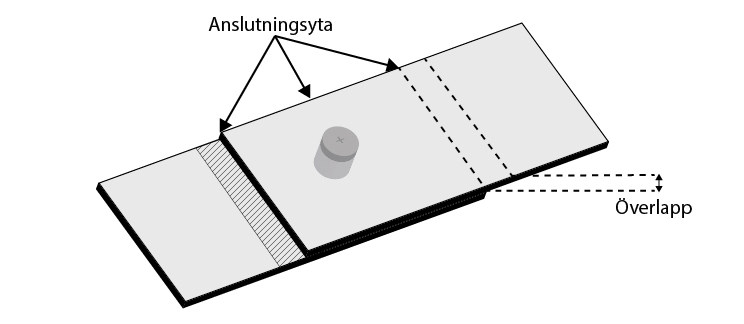
It is very important that the bonding surfaces are conductive throughout the entire life of the device. Bare non-oxidized metal may be used provided the bond is covered after mating with some corrosion protective covering (ie paint or vax). It is better to use some corrosion protected but conductive treatment of the surfaces. One way (the best) is to plate the base metal with tin. Tin oxide is soft and thus it is easily broken by the mating parts.
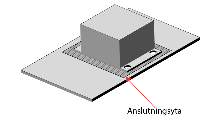
Figure 2 and 3 shows how to connect a unit (eg filters) properly to the equipment chassis. (Today only galvanized mounting plates are used in place of the former orange painted metall in OEM cabinets.)
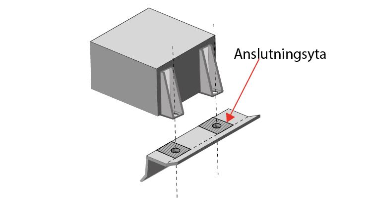
Figure 4 shows the correct mounting of a metallic connector of any type. It should be connected to the device like a coaxial connector.
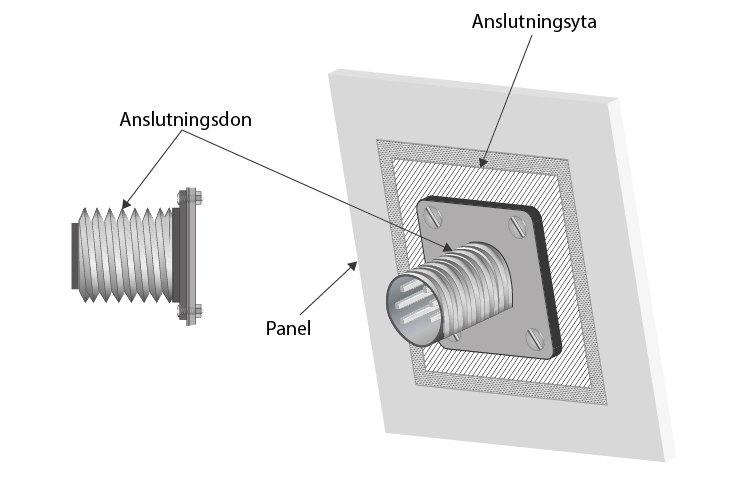
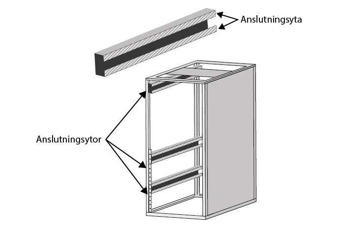
Figure 5 shows a mounting rack cabinet where all details are designed to allow low-impedance connection between the frame members and side panels as well as between the devices and the cabinet body.
In the next article we will see how to treat sources of disturbances and it´s offers and the coupling paths in between.
Miklos Steiner, Ulf Nilsson info@justmedia.se