
Preamble . Our former EMC articles reviewed four of the 5 principal conduction and radiation coupling mechanisms, as they affect equipment/ system susceptibility and emissions. The last ones (EMC Articles #6 and 7) were addressing the shielding of equipment boxes, from the smaller hand-held devices up to large cabinets or even entire rooms. The present article is covering the 5th, very important coupling mechanism: How the various disturbances that exist on the power mains (public AC distribution, ship or aircraft AC distribution, vehicle dc distribution… etc) can find their way from their source down to the electronic components of a system?
Reciprocally, some active elements in our equipments (dc-dc and ac-dc switch mode regulators, fast IGBT and thyristors, variable speed drives, fast logic circuits, etc…) can in turn become EMI sources, polluting the power distribution to the prejudice of other users. And like for the other coupling paths, many solutions that solve power line suceptibility problems will also reduce conducted emissions.
1. Equivalent Circuit for Typical Distributions
Whatever your installation, you must know at least approximately what is the wiring and grounding scheme of your power distribution, from the power source down to the users. This knowledge is important for:
- understanding and estimating the coupling factors
- understanding the CM (Common Mode) to DM (Differential Mode) conversion
- selecting the most appropriate, and economical filter
- selecting the proper characteristics for surge protection devices.
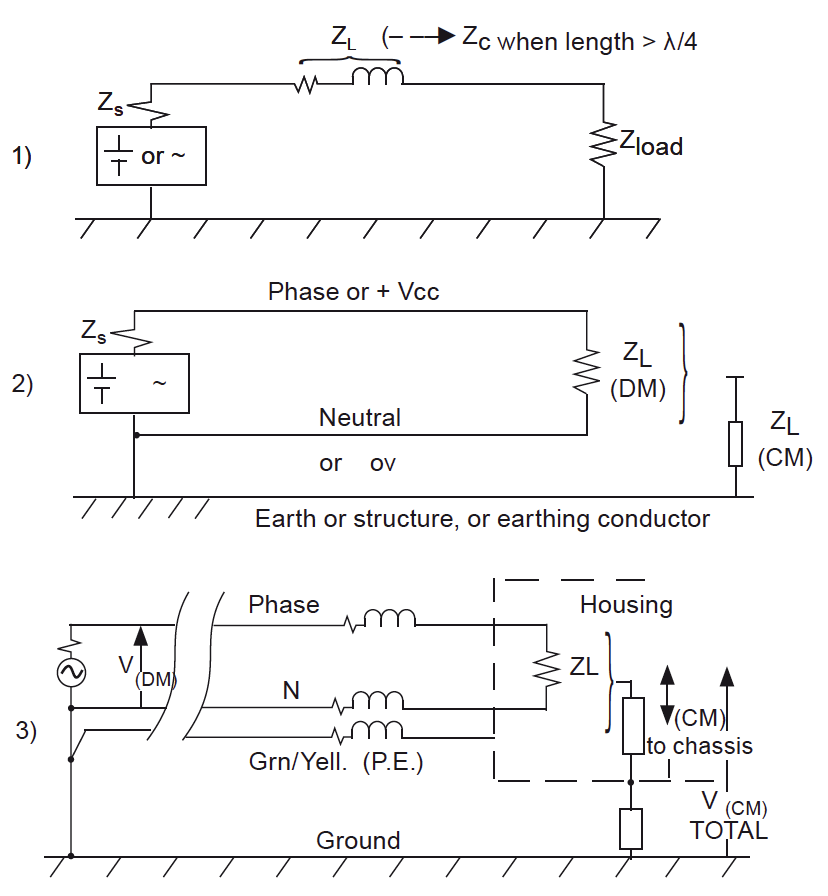
Fig.1 shows the most common configurations for power distribution schemes. Depending on the applications, a power distribution can be fairly simple: in motor vehicles the battery (+) is running in the entire harnessing, the (-) return conductor being the metallic car body. It is generally more complex with the (+) and (-), or Phase and Neutral, running together in the entire Power Distribution Network. In houses and professional buildings, the Ph and N wires are run along with a third wire, acting as a safety lifeline to the earthing electrode(s), where the Neutral of the power source (Entry Transformer or Power Plant) is also grounded. Therefore as shown on the schematic, we have in general…
Dear colleague,
This text is unfortunately locked for further reading, but you can read all Michel Mardiguian’s texts and course material about EMC in the new book ”Everything you always wanted to know about EMC but were afraid to ask”. Click for more information!
![]()