


EYE ON . It is relatively easy to achieve good attenuation (> 80 – 100 dB) of electromagnetic fields using a compact metal shield. In most practical cases, the shield is not complete, there are almost always openings, i.e. slots, windows and apertures. It is mainly these imperfections in the shield that determines the overall shielding effectiveness of the box.
The leaking shielding box
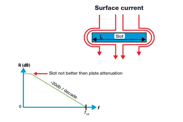
Leakage from an long, narrow opening (see Figure 1) is determined by the length of the opening compared to the wavelength. A narrow and shallow opening which length is equal to or greater than half the wavelength has no attenuation to a field at these frequencies.
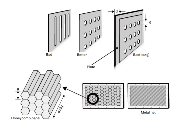
Round holes have similar impact on the shielding effectiveness.
Simplified, one can expect that the shielding effectiveness of a hole or slot increases 10 times (20 dB) per ten times lower frequency (see Figure 1). (The slope is 20 dB/decade; highest attenuation at low frequencies).
A simple calculation based on Figure 1 shows that if we want 40 dB attenuation in a slot at 300 MHz, the slot cutoff frequency fco will be 30 GHz (wavelength = 10 mm) or larger. The slot shall thus not exceed 5 mm.

If the opening is deep, i e designed as a piece of pipe or overlapping sheets, the so-called wave guide attenuation effect takes place. The field reflection attenuation of the aperture increases for frequencies lower than the cutoff frequency (fco) of the aperture as for a shallow aperture.
The wave guide attenuation effect depends on the ratio between the width of the opening (g) and depth (d) (see Figure 4). At g = d the wave guide attenuation effect gives approximately an additional 30 dB attenuation, added to the reflection attenuation as above, for frequencies lower than one third of the cut off frequency.
General design rules:
- The shield must have good electrical bonds between mating surfaces.
- Openings of various types, i e joints and vents, shall be made as small as possible.
- Openings should not exceed 1/200 of the wavelength of actual frequency, which gives theoretically 40 dB attenuation.
- It is not the area of the aperture but its largest dimension which is decisive for the attenuation.
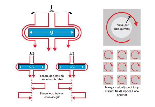
- It is better with many small openings instead of one large (see Figure 3).
- The leakage from a number of symmetrically placed holes close to each other increases with the square root of the number of openings.
- If the same number of openings are placed asymmetrically and at greater distances from each other, the leakage is greater than in the previous case.
Joints with only sporadic electrical contacts can be considered as a series of openings. To achieve the desired shielding, it is important to have a sufficient number of contacts, i e screws, contact fingers or electrically conductive gaskets (shielding gaskets).
In the next article we will talk about the cable shielding.
Miklos Steiner, Ulf Nilsson info@justmedia.se Image sources: Just Media Web Course and “Electromagnetic Shielding” by D. White and M. Mardiguian