


EYE ON . One fundamental concept in EMC design is zoning. Zoning is easy to understand. It is used in the most varied contexts and situations. Situations covering everything from old communist dictatorships, such as for example the former East Germany (DDR), to city planners and the European Union. Zones are used in order to achieve various properties in demarcated geographic areas, or within volumes. Zoning with application in electronic engineering are also known as the Controlled Electromagnetic Topology.
Zoning
First, some definitions:
- EMC = Electromagnetic Compatibility, refers to a device’s ability to function satisfactorily in its intended electromagnetic environment without introducing unwanted EM interference to this environment.
- Electromagnetic environment = The sum of all electromagnetic phenomena which exist in a given volume.
- Electromagnetic environment zone = Volume, limited by a closed surface (real or imaginary), with a specific electromagnetic environment. The electromagnetic environment in one zone differ in some respect from adjacent zones.
- Zoning is a design tool used to achieve balanced EMC solutions.
- Zones, zoning and zone boundaries are described and illustrated with simple geometric figures (see Figures 1 and 2).
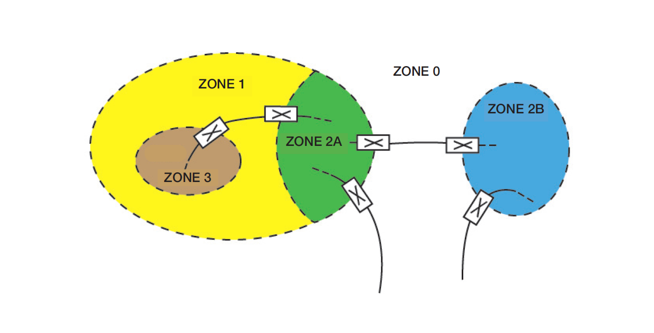
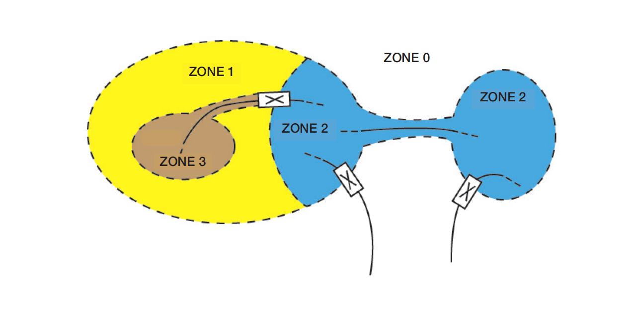
Coupling paths and coupling mechanisms are easily identified, as all coupling takes place through the zone boundary.
Disturbance can be defined as unintentional energy leakage, from a source to a victim creating unwanted reactions, interference. Disturbance often links via parallel paths. There are three main coupling types of paths: field coupling (far field), cross talk (near field) and conducted coupling. The disturbing signal often change character and transforms from one type of path to another with multitude of combination possibilities in the chain.
The boundary of a zone shall provide a reduction of the coupling for one or several electromagnetic phenomena and can be implemented in several ways (see Figure 3).
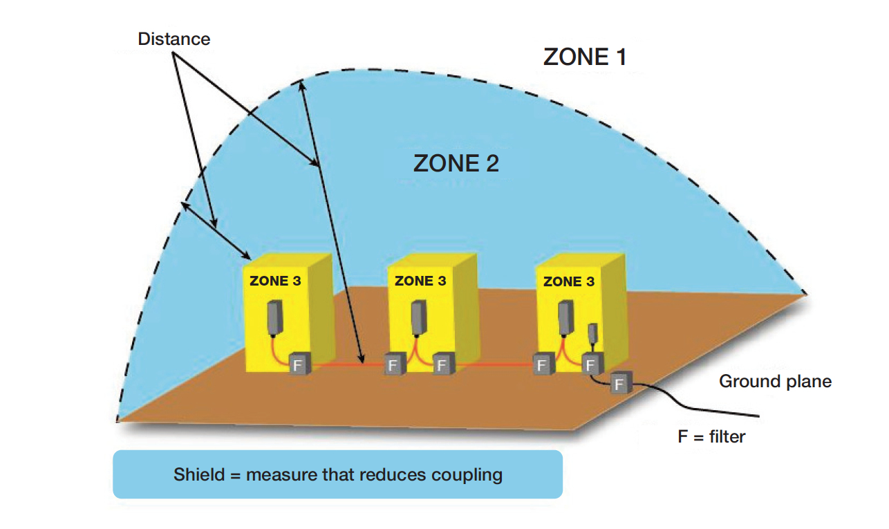
Coupling reduction may be treated as a generic shield, i. e. a measure that reduces coupling. The measures can be:
- Insulation (for example by a transformer).
- Separation by distance (field decreases with increasing distance).
- Depolarization (for example two coils which lie in parallel couple more than those which lie perpendicular to each other).
- Proximity to ground conductors, ground nets, ground planes.
- More or less covering metal enclosure, a shield, (see the next article in the series).
- Filter (work only for wires and cables).
To maintain the integrity of a zone boundary requires often several supplementary and simultaneous measures dealing with both conducted disturbance and EM-field disturbance. To reduce EM-field coupled disturbance different forms of shields are often used. To mitigate conducted interferences: use filters, surge protectors, optical couplers or transformers.
The best way to deal with conducted coupling is by the use of fiber optics. A optical fiber (and all non-conducting material) may penetrate a shield (a zone boundary) without any measures!
A filter or transformer must be located in the zone boundary (usually a shield) to be effective. A filter located on the middle of a cable, or a filter without a shield is often ineffective – and the other way around: a single conductor that passes unfiltered thru a shield can destroy the integrity of the zone boundary.
One practical application of the zoning concept on a printed circuit board (PCB) is shown in Figure 4:
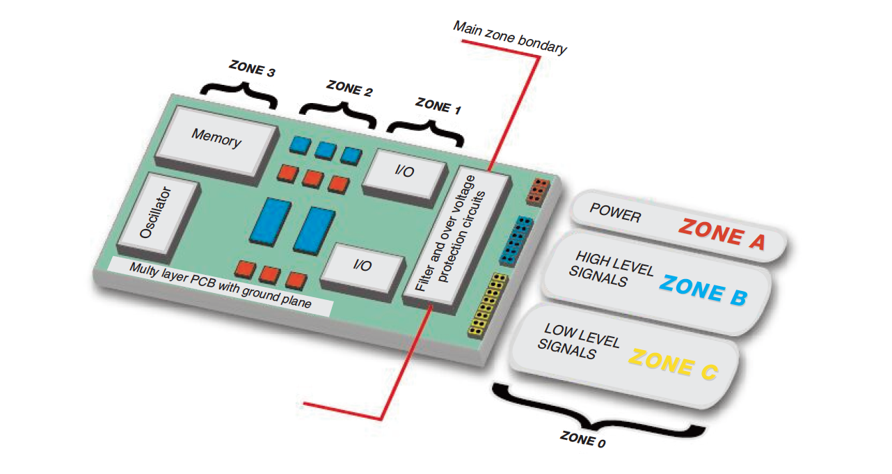
- Zone 3: Components with the highest operating frequencies are located at the furthest distance from the connectors.
- Zone 1: I/O circuits are placed next to the connectors.
- Zone 2: Circuits working at moderate operating frequencies are located between Zone 1 and Zone 3.
- The main zone border to the outer zone (Zone 0) is drawn in the middle of the filter array. All connecting wires must be filtered and, in applicable cases, protected against over-voltages.
Connecting wires can be divided into additional zones depending of the mutual EM-susceptibility and EM-emission characteristics they have.
Miklos Steiner, Ulf Nilsson
info@justmedia.se