


Background . PIM is an acronym for Passive InterModulation, an interference problem in wireless systems. The problem is not new, but has been known since long time back by designers of, for instance cell phone systems, space probes, connectors, coaxial cables, antennas and filters. The problem most frequently occurs, when dealing with high RF-currents in confined spaces. In this text, the basic theories behind PIM will be briefly discussed.
Intermodulation
Intermodulation is a process where two or more signals, having frequency components ƒ1, ƒ2, … etc, are mixed in such a way, that new frequency components, not belonging to the initial set of frequencies, are created. In some applications, for instance amplifiers, intermodulation causes distortion of the signal, and is not a desired property.
In mixers, modulators and demodulators however, intermodulation is used to shift signals from one frequency band to another. In this case, it is a desired feature.
For intermodulation to occur, two or more signals need to be multiplied. A common way to achieve this is to add the signals, and to pass the sum through a nonlinear device. To illustrate the properties of a nonlinear device, let us start with the concept of linearity. Assume we have for instance an amplifier, with input signal x(t) and output signaly (t).
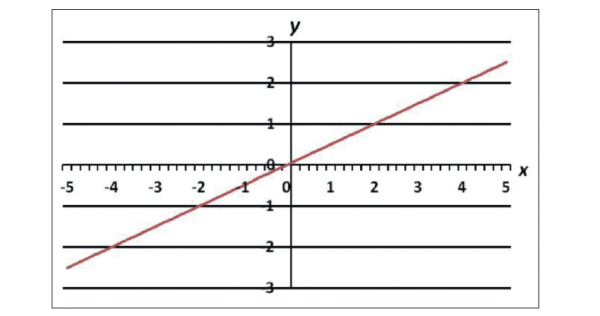
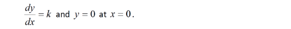
The relation between the two signals can, in a linear case, be expressed as: y(t) = kx(t), where k is the gain, which is a constant. The linear amplifier is simply a perfect proportionality, as shown in figure 1. A straight line, passing thru the origin, where k is the slope of the line.
Now, assume the input signal x(t) to the device consists of two cosine functions, with frequency ƒ1 and ƒ2 respectively:
![]()
then, the output signal will be:
![]()
The output signal only contains frequencies ƒ1, ƒ2, …, the same frequencies as in the input signal. Perfect!
Now, for the nonlinear device, say for example that the transfer function of the amplifier is:
y(t)=X3(t), i.e. the output signal is the input signal raised to three.
An example can be found in figure 2.
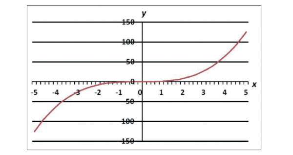
This is certainly NOT a straight line, and is therefore a nonlinear transfer
function. The formal requirements of a linear transfer function are:
If the same input signal as above is applied to this nonlinear device, the output signal will be:
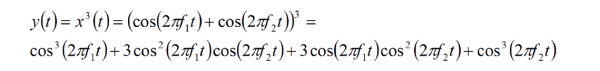
The four terms can be rewritten as:
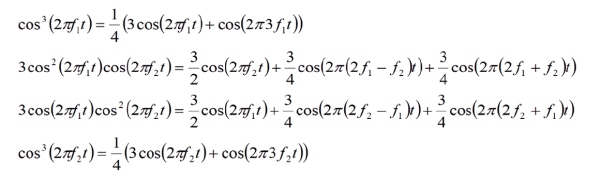
Here it is obvious that a number of new frequency components have been created. If we examine the expression above, we find:
ƒ1, ƒ2, are the original frequency components, no problem. The frequency components 2ƒ1+ƒ2, 2ƒ2+ƒ1, 3ƒ1, 3ƒ2 are quite high frequencies, compared to the desired ones, and can often be filtered out easily. But 2ƒ1 – ƒ2 and 2ƒ2 – ƒ1 pose problems, since they are close to the desired frequencies, and cannot be removed using filters.
In this case, the nonlinearity had the exponent 3, and the frequency of the problematic intermodulation products were 2ƒ1 – ƒ2 and 2ƒ2 – ƒ1. If the exponent had been 5, the problematic frequencies would have been 3ƒ1 – 2ƒ2 and 3ƒ2 – 2ƒ1. For exponent 7, 4ƒ1– 3ƒ2 and 4ƒ2 – 3ƒ1 would be created. In the general case, this group of intermodulation products, can be expressed as ƒIM = mƒ1 – nƒ2, where m and n are integers.
The order of the intermodulation products are obtained as m + n. So far, only odd exponents, i.e. intermodulation orders have been studied. It is an interesting fact, that even numbered orders never produce frequency components close to the desired, original frequencies, and therefore, in most cases do not present a problem.
Nonlinearities
The nonlinear mechanisms considered in this context are passive. Passive means that the device does not have a power supply. Examples: connectors, cables, antennas etc. It may even suggest that mechanical, non-electric parts, e.g. cable clamps, handles and bolts can act as passive nonlinearities. Nonlinearity often gets more pronounced at higher signal levels, i.e. strong RF-currents. There are basically two situations, where a part may carry strong RF-currents.
The first case is conducted current. Current originating from e.g. a strong radio transmitter. A typical situation is RF-current flowing in cables, connectors, cable joints and antennas. If, for instance, a connector act nonlinearly, intermodulation products may be created.
The second case is current induced by radiation. Metallic parts in the vicinity of a transmitter antenna, will pick up RF-power from the electromagnetic field and convert it into a RF-current in the part. If the part has a nonlinear behavior, intermodulation products may occur, which will then be reradiated as wireless interference.
But why do metallic parts have nonlinear current behavior? There are mainly two mechanisms involved. The first one is the properties of the conducting material itself. For example, some magnetic materials may exhibit a nonlinear performance, due to the fact that the current causes magnetic fields, and that magnetization curves are nonlinear for strong currents. In other cases, the nonlinearity of a material may be caused by polarization issues.
The second mechanism is caused by surface effects in the interface between two materials. For example, oxidation on a contact surface may contribute a MIM-diode. MIM stands for Metal-Insulator-Metal. This is a nonlinear quantum effect. MIM-diodes suffer from poor mechanical stability, but they can operate at very high frequencies, above 10 THz. They have also been considered for solar energy conversion. So, to avoid PIM problems, select materials carefully, and keep your connector surfaces clean from oxide and dirt.
Pim in practice
We will use a typical GSM base station to illustrate the practical problems with PIM. The GSM system is a full duplex system, which implies that all transmitters and receivers will operate simultaneously. To avoid interference, different frequencies are used. In for instance the PGSM- 900 band, an uplink band is defined between 890.0 – 915.0 MHz, and a downlink band between 935.0 – 960.0 MHz. The uplink is from the handset to the base station, and the downlink the other way round.

Typically, we will find a number of pretty strong radio transmitters transmitting in the downlink band, while a number of sensitive radio receivers operate in the uplink band. Obviously, we do not want any signals from the downlink to interfere with the delicate signals in the uplink. As long as everybody stays on their allocated frequency, all will work fine. However, intermodulation has the nasty effect of creating new frequencies that are not expected…
The downlink band harbors 124 channels. If we transmit on p channels, there may occur p(p–1) problematic intermodulation products. This means that in worst-case, 15252 intermodulation products will be generated. This is a simplified example, in reality there are many more frequency components to take into account (due to the modulation of the signals). Often, the intermodulation products may not be experienced as discrete frequencies, but rather as a general increase in the noise floor.
Where in the frequency band may the intermodulation products show up then? Doing some calculations, varying the transmitting frequencies ƒ1 and ƒ2 from the lower to the upper limit of the downlink, we can find the location of the intermodulation products. For third order products the frequency of the intermodulation products are given by 2ƒ1 – ƒ2 and 2ƒ2 – ƒ1, for the fifth order by 3ƒ1 – 2ƒ2 and 3ƒ2 – 2ƒ1 and for the seventh order by 4ƒ1 – 3ƒ2 and 4ƒ2 – 3ƒ1.
As can be seen in figure 3, the intermodulation products occur pair wise and symmetrically round the downlink band. Yellow is the downlink. Purple is the third order, blue fifth order and pink seventh order intermodulation products. (Only intermodulation products outside the downlink band shown).
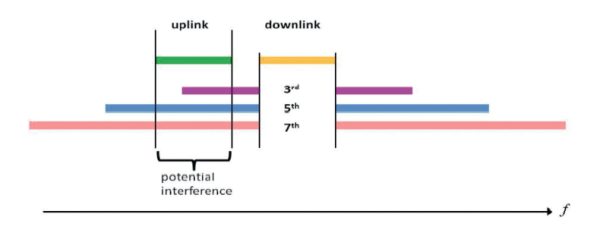
products outside the downlink.
The green band in figure 3 is the uplink. It is clear that the frequency range of the intermodulation products overlap considerably, and that the risk for interference is imminent. Raising the noise floor, in the sensitive uplink, degrades the performance of the radio links and the base station, thus reducing the revenue. So, at last, a word of wisdom: Stay linear!
Dag Stranneby
Dag is performing PIM studies at Campus Alfred Nobel, Örebro University, in collaboration with Nolato AB in Hallsberg, Sweden. More information can be found at: http://vimeo.com/dstranneby/pim