

EMC testing . of autonomous vehicles is challenging because the involved systems are designed to identify unrealistic driving conditions, which is exactly what we have in a typical anechoic EMC chamber. When the system detects unrealistic conditions, autonomous driving functions are disabled or set to predefined states, which means that EMC testing of autonomous functions is not possible. To fully test autonomous driving systems, we therefore need to emulate a realistic environment in many aspects, i.e., we need to stimulate involved sensors in a realistic way.
To address this, Volvo Car Corporation, Rise and Provinn, initiated a project partly financed by Vinnova within the FFI-program. In the project, it was demonstrated that it is possible to stimulate radars and cameras used for active safety systems, and to simulate the vehicle position by transmitting a synthetic GNSS (Global Navigation Satellite System) signal in the chamber, so that realistic EMC testing of a complete vehicle can be done for systems using these sensors.
Introduction
As autonomous driving applications are emerging it is of vital importance that the underlying functions perform as intended in all possible situations. The involved systems are multi-sensor dependent and safety critical. Thorough tests are needed before such systems are put on the market. This includes EMC testing.
In the automotive industry, EMC tests are today carried out on component, subsystem and complete vehicle levels. However, when testing on complete vehicle level it is often difficult to fully activate a multi-sensor function in a laboratory environment. This is because many functions are intelligent in the sense that the algorithms are designed to identify unrealistic sensor input and if detected the function is disabled or set to a predefined state. To fully test such complex functions, we need therefore to emulate a realistic environment in all necessary aspects, i.e., we need to stimulate all sensors including radars, cameras, lidar and GNSS. If the sensor environment can be successfully emulated in the EMC chamber, any function based on the sensors data can be verified.
As a first step in finding methods for stimulating the various sensors, the two-year project eVAMS (EMC VAlidation of Multiple Sensor Systems, Vinnova ref. 2015-06892) was initiated. The scope of the project was to develop methods for stimulating radars, cameras and GNSS. To evaluate how successfully the environment was emulated, the behaviour of three driver assistance functions was monitored. These functions were Adaptive Cruise Control (ACC), Lane Keeping Aid (LKA) and Pilot Assist (PA), as implemented by Volvo Car Corporation in the 2016 XC90. These functions, together with GNSS, play an important role for automation and therefore form a firm foundation to build future test procedures on, and to establish a road map for developing EMC testing of autonomous vehicles.
Strategy for vehicle EMC testing
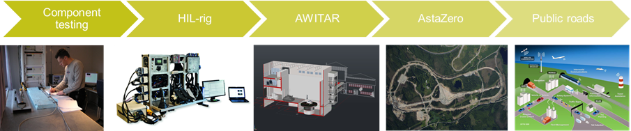
The ultimate goal for any vehicle manufacturer is to guarantee the safety and satisfaction of their customers. One part of this is to fulfill governmental and legal requirements and recommendations. For instance, the US Department of Transportation (DOT) and the National Highway Traffic Safety Administration (NHTSA) propose manufacturers to develop well defined and documented processes that demonstrate the performance and safety of automated functions [1]. Every function and hardware component should be tested in the most appropriate way. It is however up to the vehicle manufacturer to decide on which level to perform the testing. The different test levels are depicted in Fig. 1, ranging from component level testing to testing on public roads. The complexity of the test often decreases for lower test levels.
The exact details of the test strategy is up to each vehicle manufacturer to define and is something that is normally not shared in public. Referring to Fig. 1, the eVAMS project was focused on future complete vehicle EMC testing in the new semi-anechoic chamber AWITAR at RISE [2].
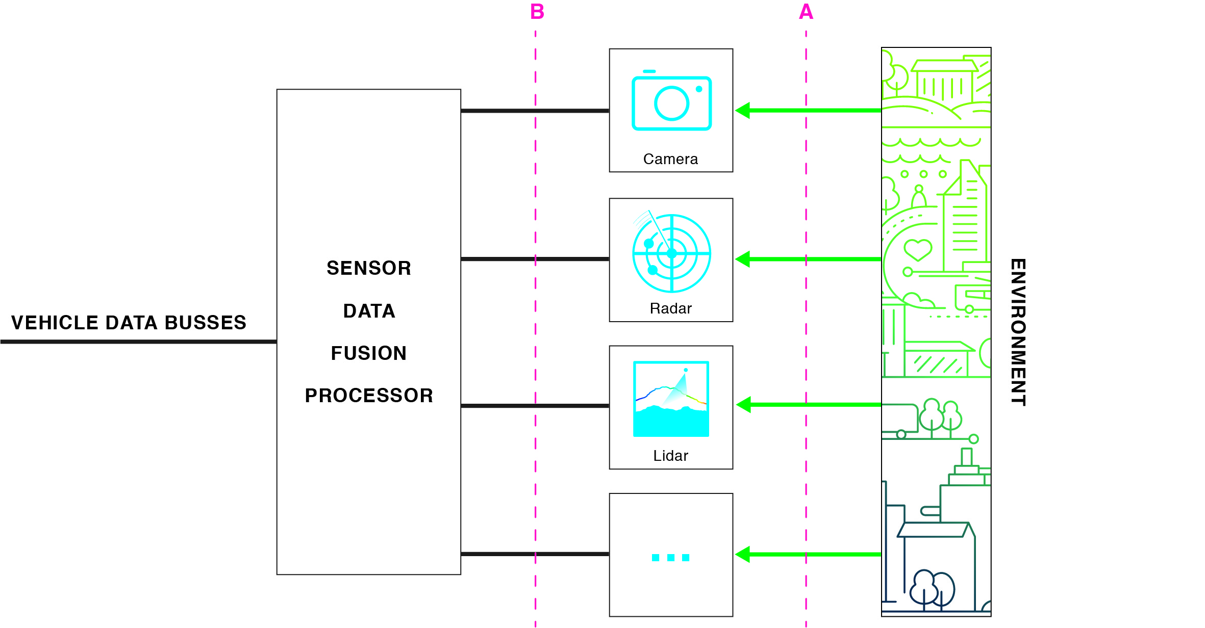
For component level or simple function testing it is often sufficient to simulate input to only one sensor, while for complete vehicle and complex function testing several sensor inputs need to be simulated. In the latter case, the sensor stimuli also need to be synchronized to each other. This is perhaps the most difficult to achieve. While synchronizing radar and camera stimuli is a challenge in itself, including inertial and GNSS sensors is a much more complex task. In the latter case one option is to instead simulate the output from one or several sensors, i.e., shifting from interface A to B in Fig. 2.
This is something that is often done in HIL-rig testing but can also be applied when doing complete vehicle testing. It should however be noted that in this case the whole system is actually not tested. This may however be perfectly alright if the not included sensor or component has been tested on a lower level. System validation is often accomplished by using a chain of tests.
Radar
Modern vehicles normally have several radars. This project considered only the forward-looking radar and the adaptive cruise control (ACC) function which is based on this radar. The radar frequency is 76-77 GHz and the principle of operation is FM-CW, i.e., a frequency ramp is transmitted. This technique provides both the distance to the target as well as the relative speed, i.e., both distance and speed need to be emulated. The function of the ACC system is to adapt the speed to keep a safe distance to a slower vehicle in front. Our approach to emulate a radar environment was to move a radar reflector from side to side in front of the vehicle.
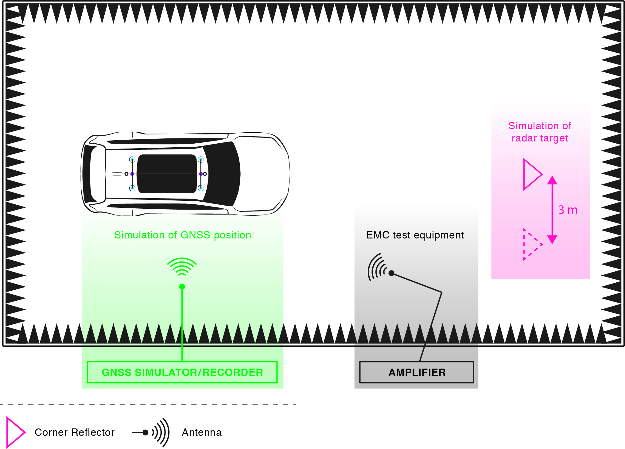
The test setup is shown in Fig. 3. This would simulate a vehicle moving in and out of the lane in front of the test vehicle. If the emulation is successful, the ACC function would operate as anticipated, i.e., decrease the speed when the target moves into the same lane, and to increase the speed again when the target disappears. This behavior was also successfully produced when using the Fig. 3 setup in our anechoic chamber.
More complex scenarios, e.g., several target vehicles at different distances and with different relative speeds, can be simulated by using an active radar target simulator. Such simulators basically take the received radar signal, add delay and Doppler shifts and re-transmit it. In the eVAMS project, we tested two different active radar target simulators provided by Rhode & Schwarz and Anritsu.
Camera
The camera is in principle equivalent to the driver’s eyes, therefore our vision and perception is a natural benchmark of the system performance. What we can see and interpret, we expect the car to see and interpret in the same way. The expectations on a camera based system are therefore very high. On the other hand, it also means that we have the experience how to stimulate the sensor (camera). If the sensor stimulus looks good to our eyes, it would probably also be good enough for the sensor. It should however be pointed out that a camera might have the capability to detect other wavelengths than the human eye. It might, e.g., detect animals or pedestrians in the dark that we cannot see.
The LKA system studied in the eVAMS project uses the camera as the only sensor to detect lane markings. When the vehicle departs the current lane without an activated turn indicator, LKA applies a torque to the steering wheel that helps the driver to steer back into the lane. If the steering intervention is not enough to keep the vehicle in the lane, the driver will be alerted by vibrations in the steering wheel.
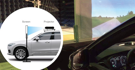
To stimulate the camera during EMC testing, a roof mounted projector projecting a video on a screen placed over the engine hood was used, see Fig. 4. The video showed a scenario where the vehicle slowly approached and crossed the lane markings, which would under normal conditions result in a steering action from the LKA system. The video was created in a special computer program that is also used for creating videos for HIL-rig testing, thus making it possible in the future to compare the two different test approaches and to re-use and share resources and equipment. With the setup described above, the XC90 produced lane departure warnings and steering aid as expected in real-world driving, while subjected to electromagnetic fields.
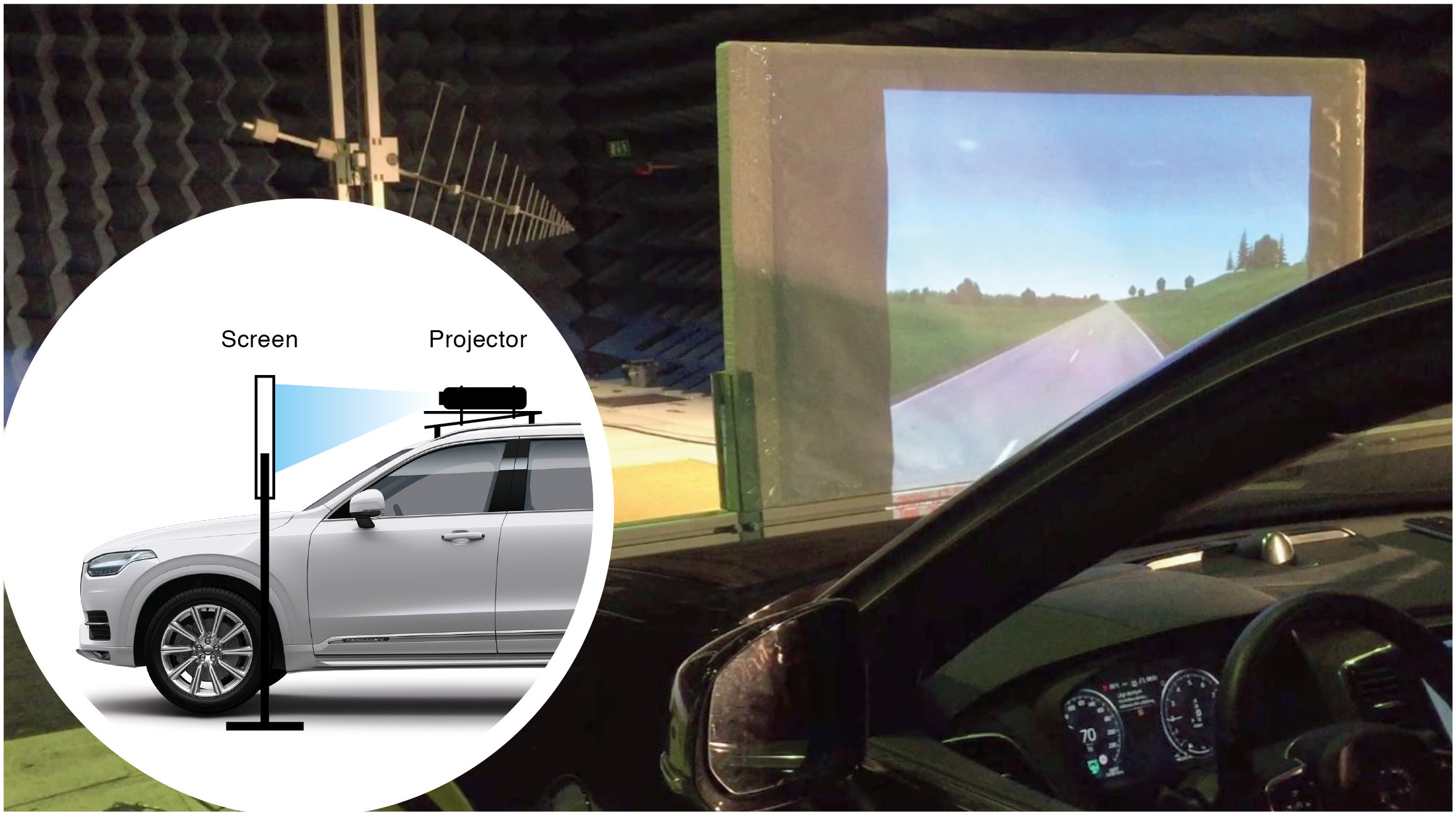
While LKA helps prevent lane departure, the function Pilot Assist (PA) provides steering torque which helps keeping the vehicle in the center of the lane. PA uses both radar and camera and can thus be tested by combining the two setups for radar and camera. By using a radar transparent screen for the video projection, the radar (located in the wind screen) could be stimulated independently of the camera. As with LKA, the PA function provided the expected steering aid with the setups in Fig. 3-4.
GNSS
Some future driver support systems, and for that matter existing ones such as some adaptive cruise control implementations, use positioning data from GNSS (Global Navigation Satellite System) to support the vehicle in understanding the terrain and traffic ahead. One application that exist already today is to select gear and adjust the speed of the vehicle to achieve optimum economy whilst driving in a hilly terrain [3]. If the up and downward gradients along the route can be anticipated by the help of GNSS, this gives especially for heavy vehicles a considerable fuel saving for the benefit of the truck owner as well as the environment. Any future functions involving autonomous navigation will likely use GNSS to a large extent.
To test the GNSS functionality during an EMC test in a shielded chamber we need to inject satellite RF-signals in the chamber. The easiest way would be to simply place an antenna outside of the chamber, amplify this signal and re-transmit it in the chamber. This would only give a static position and would for a dynamic system test not be good enough. For a realistic system testing, a signal that mimics a dynamic satellite constellation simulating the vehicle moving along a pre-defined route need to be created. This can be done in two ways, either by recording satellite signals when driving on the road and then re-play this signal in the EMC chamber, or using a GNSS simulator to generate the signal based on a route defined in, e.g., Google MapsTM. In the eVAMS project both methods have been tested by using different equipment provided by Spirent. As depicted in Fig. 3, the satellite RF-signal is transmitted in the chamber by using a single antenna. The car’s navigation system showed the correct location on the map and could track the position as it changed.
The simulated GNSS signals were not synchronized with the dynamometers, i.e., the movement of the wheels. The navigation system in the vehicle does not only use GNSS for positioning, but also other sensors such as wheel sensors for dead reckoning and a smoother position tracking. When starting a test, the vehicle has a certain simulated position, and as the wheels are spinning on the dynamometer the satellite constellation should be altered so that the simulated position is following the defined route, tracking the distance travelled. To achieve this the dynamometer must control the GNSS simulator.
Summary and outline for future work
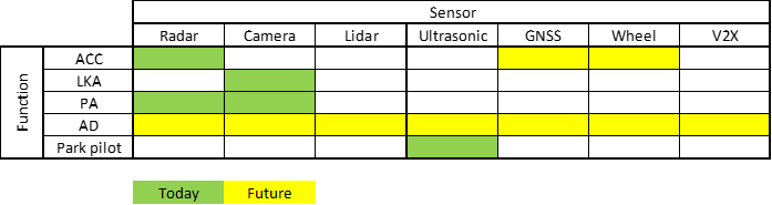
In the eVAMS project it was demonstrated that it is possible to emulate a realistic environment for radars, cameras and GNSS sensors, so that realistic EMC testing of a complete vehicle can be done in an anechoic chamber. The successful emulation of sensor environment was confirmed by observing normal behaviour of the functions adaptive cruise control (ACC), lane keeping aid (LKA) and pilot assist (PA). Remaining tasks for the future include to find methods for synchronizing stimuli for the various sensors and to find methods also for other sensors, such as lidar, ultrasonic etc. Table 1 shows a sketch of which sensors are involved in different automated functions, and thereby also the need for synchronization of sensor stimuli. The next step for the future is to develop the missing methods on all levels of testing illustrated in Fig. 1, and the process of demonstrating the performance and safety of autonomous vehicles.
Acknowledgement
This work has been partly supported by the Swedish Governmental Agency for Innovation Systems (Vinnova) within the FFI program Electronics, Software and Communications. Partners have been Volvo Car Corporation, RISE (former SP Technical Research Institute of Sweden), and Provinn AB.
(1) Björn Bergqvist, (2) Jan Carlsson, (3) Henrik Toss, (2) Torbjörn Persson, (1) Andreas Westlund (1) Volvo Car Corporation (2) Provinn AB (3) RISE Safety and Transport/Electronics
References
- US Department of Transportation, National Highway Traffic Safety Administration, “Federal Automated Vehicle Policy – Accelerating the Next Revolution in Roadway Safety”, Sept. 2016.
- AWITAR – Automotive Wireless Test and Research Facility
- Volvo Trucks
- NHTSA – National Highway Traffic Safety Administration
- Euro NCAP