


Our former . EMC articles reviewed the principal conduction and radiation coupling mechanisms, as they affect equipment/system susceptibility, and the last one (EMC Article #5, June Issue) was addressing Shielded Cables. The present article is focusing on the shielding of equipment boxes, from the smaller hand-held devices up to large cabinets or even entire rooms.
Someone may wonder why treating separately cables shielding and box shielding? Against an EM field a shield is a shield, no matter if it is a tube or a cube … In fact, there is a significant difference: in a shielded cable, the wires are closely coupled with their tubular envelope, such as it is the mutual inductance that does the cancelling effect. In a shielded box there is no such close coupling: it is the portion of the field that goes through the barrier that gives a measure of the shield effectiveness. This long ”Box Shielding” article has been split in two parts.
Part 1 (Sept. issue of EE) addressed the basic approach for successful shielding: defining the objectives and selecting the proper material and thickness. This Part 2 describes the methods/hardware for obtaining the desired Shielding Effectiveness by controlling the various leakages.
4. Shield degradation caused by apertures
All the SE figures given above assume a plain, homogeneous barrier. Real life housings are never made like continuous metal cubicles: they have slots, seams and other apertures that inevitably leak. As for a chain, a shield is only as good as its weakest link; therefore it is important to know the shield’s weak points in order to match realistic objectives.
- At low frequencies, what counts is the nature of the metal (conductivity, permeability)and its thickness.
- At high frequencies, where any metal would provide SE of hundreds of decibels, such figures are never seen because seams and discontinuities completely spoil the metal barrier (Fig.5).
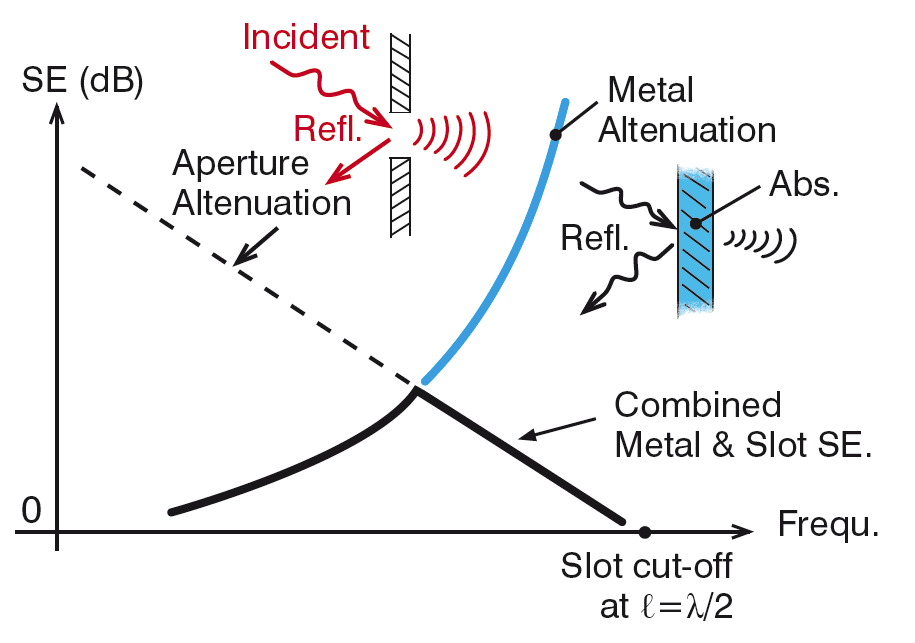
4.1 Attenuation of one single aperture
A slot in a shield can be compared to a slot antenna that, except for a 90° rotation, behaves like a dipole. When slot length reaches λ/2, no matter how small the height (h), this non-intentional antenna behaves as a perfectly tuned dipole, i.e., it reradiates on the “exit” side all the energy that excites the slot on the incoming side. It may even exhibit a slight gain of about 3 dB. Below this resonance, the slot leaks less and less as frequency decreases. The equivalent circuit for a slot is an inductance (Fig. 6), until it resonates with the edge-to-edge capacitance, when ℓ = λ/2…
Dear colleague,
This text is unfortunately locked for further reading, but you can read all Michel Mardiguian’s texts and course material about EMC in the new book “Everything you always wanted to know about EMC but were afraid to ask”. Click for more information!
![]()