

EMCCOM . was a three year VINNOVA financed FFI project within the Vehicle Development program. EMCCOM started 2012-09-14 and ended 2015-06-30. The project had a total budget of 7,3 MSEK. Partners in the project were Volvo Cars, Volvo AB, Provinn AB, FOI Swedish Defence Research Agency and SP Technical Research Institute of Sweden.
EMCCOM has developed new EMC test methods for vehicle electronic units and simulation models . Both to be used to protect the performance (both reliability and capacity) of wireless digital communication services in vehicles and by that ensure high availability of implemented safety and transport efficiency functions. Questions that were addressed in the project include:
- Which detector has the best correlation between a Radio Frequency (RF) electromagnetic interference measurement and the resulting degradation of wireless system performance?
- What level of electromagnetic interference is acceptable for a wireless communication system in a vehicle?
- What level of electromagnetic emission is acceptable for an electronic control unit to be used in a vehicle?
- What measurement method (detector, resolution bandwidth, …) is best suited to characterize the RF electromagnetic emissions from an electronic control unit to make it possible to predict the resulting performance degradation of an exposed wireless communication system?
- Is it possible to develop very simple models to be used to predict the performance degradation of an exposed wireless communication system?
Systems that have been studied are 3G, 4G, GNSS (GPS), WLAN (802.11g), C-ITS (802.11p).
The results have shown that:
- Best overall correlation have the RMS detector for the studied technologies and frequency bands with an average Pearson correlation coefficient of 0,88. The Average detector is however not far behind, 0,86.
- Acceptable level of electromagnetic interference is a concept containing many underlying standpoints. What data rate is needed and by that, what modulation? How much error correction is acceptable to use for this single type of interference? In the result from the EMCCOM measurements the standpoint have been highest modulation and lowest code rate as a basis.
- Based on the measurements simple binary logistic regression models have been developed that can be used to predict the resulting probability of error (BLER or PER) from an interfering signal. These simple models have been developed in parallel to more complex models to understand the underlying mechanism for a technology to be disturbed.
The result of the project will be used in the work to update existing international standards aiming at the protection of radio receivers on board vehicles. In fact, the project has given input to the standardisation working group CISPR/D/WG2 in the form of a white paper.
Background
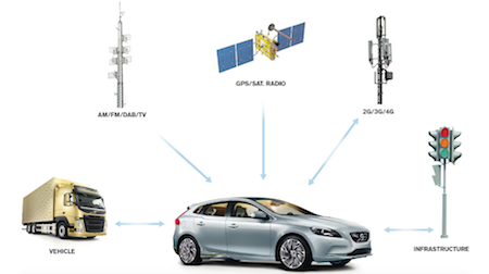
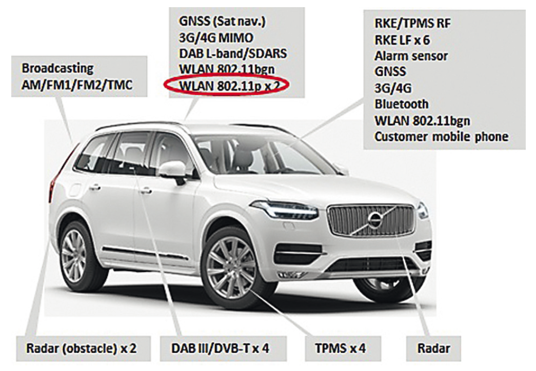
In the beginning of 2012, when the application for EMCCOM was written, Volvo Cars and Volvo AB for a longer time had experienced the need of deeper knowledge about how electromagnetic emissions from modern vehicle electronics degrade the different wireless communication systems used in vehicles. Modern vehicles contain several different broadcasting and communication radio systems that are used both for entertainment and vehicle functions. In Figure 1, an example of different systems used in a Volvo car now or in the near future is shown.
The development goes towards more complex safety functions and autonomous vehicles. Examples of such functions are the Use Cases described at the Car-2-Car communication consortium home page (https://www.car-2-car.org):
- Location warning
- GLOSA (Green Light Optimal Speed Advisory)
- Motorcycle warning
- Warning lights on
- Warning of roadworks
- Avoidance of traffic jams
Functions like these require information from “off board sensors”, sensors not located in the vehicle itself. These sensors can be positioned on other vehicles or in the infrastructure close to or far away from the vehicle. In order to maintain high availability of functions, communication link performance metrics such as range and signal delay have to be addressed to a higher degree than in traditional entertainment broadcasting radio systems.
In order to increase the knowledge, develop new requirements and test methods as well as low complexity simulation models to be able to predict how the link performance is affected by electromagnetic emissions from the vehicle electronics, the EMCCOM project was started.
Measurements and results from EMCCOM
In the EMCCOM project, measurements were conducted on several digital radio systems with the aim to find acceptable interference levels at the radio receiver input. Several different types of interference signals were used as test signals. Measurements were performed on the following systems and frequencies:
- 3G (WCDMA), 2112.6 MHz, 16 QAM, Code rate 0.97, 14 Mbit/s
- 4G (LTE), 2140 MHz, 64 QAM, Code rate 0.94, 75 Mbit/s
- WiFi (IEEE 802.11g), 2450 MHz, 64 QAM, Code rate 0.75, 54 Mbit/s
- ITS (IEEE 802.11p), 5900 MHz , QPSK, Code rate 0.5, 6.0 Mbit/s
The highest modulation and lowest code rate were used as a basis for our measurements. The philosophy behind this was that the vehicle shall not degrade the potential of the communication technology. If the performance is degraded, it shall be due to other factors than emissions from on-board vehicle electronics.
The acceptable interference level was determined in the following way;
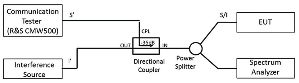
- The signal (S), see fig 3, was adjusted to a level 10 dB above the threshold level, i.e., where the throughput goes from 100% to 0% (very sharp knee). This corresponds approximately to the “edge of service” for each system with the above given modulation, code rate etc.
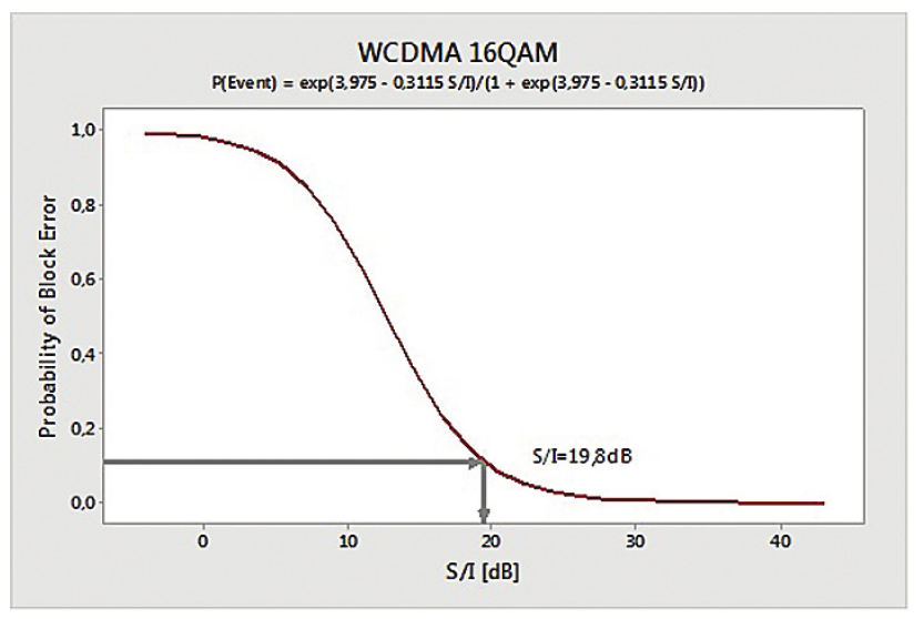
- Probability of Block Error (BLER) or an equivalent measure (system dependent) was measured as a function of signal to interference amplitudes (S/I) for each type of interference signal.
- A binary logistic regression model, taking all interference types into account, was made. An example of regression model for WCDMA is shown in Fig. 2.
- From the regression model, the signal to interference level at 10% BLER was derived. This level defines the acceptable signal to interference level at the radio receiver input.
- The acceptable interference level in dBm is then computed as the threshold level + 10 dB – S/I from the above step.
- This level is finally converted to the acceptable voltage at the receiver input, assuming 50 ohm by adding 107 dB.
Measurement setup
In order to have a well-defined measurement setup we have used a conducted measurement setup, as shown in Fig. 3. In principal, the same setup has been used for all tested radio systems. For GPS and C-ITS the Communication Tester was changed to a GPS simulator and a Transmitting IEEE 802.11p node respectively. The measurements are static in the sense that fading is not included.
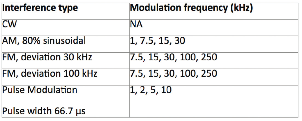
Tested interference signals
The tested interference signals are defined in Table 3.
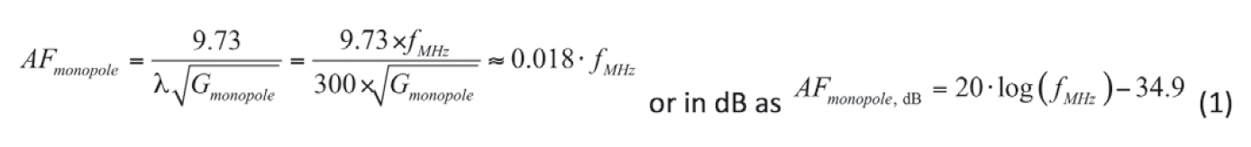
Assumptions used for deriving limit lines
The measured quantity was the acceptable level, in dBμV, at the input of the radio receiver, as defined above. In order to compute the component requirements as in IEC CISPR 25, in dBμV/m, we have used the antenna factor for a quarter wavelength monopole. We have used this antenna factor for all frequencies. The rational for this choice is that this is the “best possible” antenna for vehicle applications and is normally the design goal when designing an automotive antenna. The antenna factor we have used is thus given by equation (1);
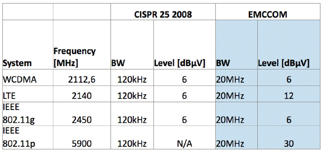
Measureme nt results and comparison IEC CISPR 25
The acceptable voltage at the receiver input calculated as above then becomes:
Based on vehicle limits above and using the antenna factor in (1), the corresponding component limits become:
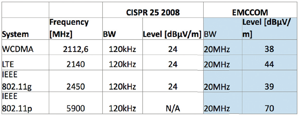
It should be noted that the IEEE 802.11p radio used in our measurements was a prototype based on a modified IEEE 802.11a transceiver.
Measurement detector and bandwidth
Correlation between measured amplitude of the interference signal, I, and the probability of error (BLER or PER) was calculated for Peak-, RMS- and Average-detector.
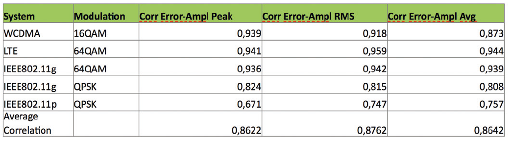
interference amplitude using 3 different spectrum analyzer detectors:
Peak, RMS and Average.
A measurement bandwidth of 20 MHz has been used during the measurements. Recommendation is to use:
- Use the bandwidth of the radio system. Problem: measure ment noise can be too high. Not all spectrum analyzers have the needed RBW.
- 1 MHz is a compromise that is acceptable for the noise sources present in the cars today.
- In case the measurement noise is to high, decrease the bandwidth down to 120kHz or 10kHz to get required margin between measurement noise level and requirement level.
Björn Bergqvist, Volvo Cars Torbjörn Persson, Provinn AB
References
- [1] S. Örn Tengstrand, K. Fors, P. Stenumgaard, K. Wiklundh, “Jamming and interference vulnerability of IEEE 802.11p”, EMC Europe 2014, Gothenburg, Sweden, 1-4 Sept., 2014.
- [2] P. Ankarson, U. Carlberg, J. Carlsson, S. Larsson, B. Bergqvist, “Impact of Different Interference Types on an IEEE 802.11p Communication Link Using Conducted Measurement”, EMC Europe 2014, Gothenburg, Sweden, 1-4 Sept., 2014.
- [3] S. Örn Tengstrand, P. Stenumgaard, ”Performance Estimation of DSSS Wireless Systems in Impulsive Interference”, Accepted for presentation at IEEE/EMC Europe 2015, Dresden, Germany, 18-22 Aug., 2015.
- [4] P. Ankarson, J. Carlsson, B. Bergqvist, S. Larsson, M. Bertilsson, “Impact of Different Interference Types on an LTE Communication Link Using Conducted Measurements”, Accepted for presentation at IEEE/EMC Europe 2015, Dresden, Germany, 18-22 Aug., 2015.
- [5] Dengzheng Huang, Ragad Majeed, “Development of IEEE 802.11p Transceiver in Simulink & Evaluation of the Electromagnetic Interference Effects” Report number: EX047/2015, Master thesis at Department of Signals and Systems, Chalmers University of Technology Göteborg, Sweden 2014
- [6] B. Bergqvist, T Persson “Vehicle development-an EMC challenge” Electronic Environment #3 2013
- [7] B.Bergqvist, K. Kilbrandt, P. Ankarson, J. Carlsson “CISPR/D/ WG2 N315-Comments on CISPR/D/WG2 N296” 2015-05-13