

Radiation Paths and cable-to-cable coupling . This is the 4th article of our EMC awareness series. The former articles, after a broad overview of the EMC subject, reviewed the principal Civilian and Military Norms and test methods, insisting on the legal inforcement of these verifications in Europe, where they are turned into mandatory, « must-comply » laws. Given that source/coupling path/victim concept is the basic approach to EMC, most of the time it is the coupling path between the culprit source and the victim equipment wich is the crux of the problem, hence of its solutions. The 5 essential coupling mechanisms were listed, by which EM Interference take place. Although any equipment can be alternately the victim, or the source, of an EMI problem, we focused on EM susceptibility as being the manifestation that appears first in the designer’s or field engineer’s worries.
Nevertheless, emissions problems sooner or later may show-up, but since coupling mechanisms are reciprocal, the author has taken the choice of always reviewing susceptibility situations first, because once understood, the comprehension of emission mechanisms would follow easily.
The 3rd article treated the very common mechanism of Common Impedance Coupling, one that probably ranges at the top of the list for causing EMI problems. The present, 4th article is reviewing two coupling paths where the culprit and victim circuits are not in physical contact and the parasitic effect occurs through radio propagation or near-induction coupling (Crosstalk).
1. Field-to-cable Coupling
Although neither considered as antennas or designed for, cables and printed circuit traces are unintentional antennas. Any piece of conductor carrying a current (or excited by a voltage) will radiate an electromagnetic field. Reciprocally, any piece of conductor illuminated by an ambient electromagnetic field will exhibit a current flow and a related voltage. Such unintentional, antennas can be broken-down in two simple forms: closed loops or open-ended wires.
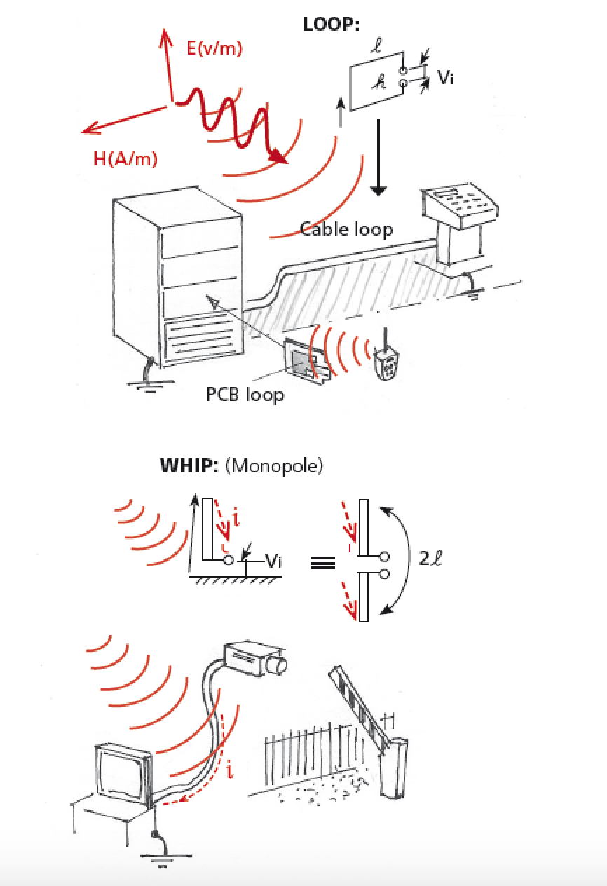
A loop is intuitively regarded as magnetic field (H-field) sensitive, but in fact it responds to both E and H fields, with a predominant ability to privilege one or the other depending on its orientation versus the field vectors and propagation. Open-ended wires are generally regarded as E-field sensitive, yet both shapes can pick-up signals from an electromagnetic field, expressed in Volts/m.
Most often, real-life circuits and cabling configurations are neither purely open wires or perfect loops, but somewhere in-between. Circuits that are terminated into high impedances (> 377Ω) tend to behave as dipoles or whip antennas, while those terminated in low impedances (< 377Ω) tend to behave as…
Dear colleague,
This text is unfortunately locked for further reading, but you can read all Michel Mardiguian’s texts and course material about EMC in the new book “Everything you always wanted to know about EMC but were afraid to ask”. Click for more information!