

Part 1: Conduction Paths . As briefly described in our introductory Article N°1 ( Issue #2-2015 of EE Magazine), ElectroMagnetic Interference is a Source/Coupling Paths/Victim situation, the basis for an overall understanding of EMI control in order to reach a satisfactory level of compatibility (EMC). We also said that reducing the interference at the source itself, or at the victim’s levels, were most of the time unpractical. Therefore, the only remaining area for action is in general the coupling path, which implies understanding the coupling mechanism.
Preamble
This article and several of the 10 articles to come will focus on the essential EMI coupling mechanisms:
- Understand them qualitatively, with sometimes a calculated estimate helped by simple numerical examples of real cases.
- Prevent them by proper design guidelies (or fix them if too late..) We will start by paying attention to Susceptibility / Immunity cases, since it is often the engineer’s main concern, even if this is questionable. Then we will naturally address Emissions problems, which will become easy because ALL the EMI mechanisms are reversible.
1. The first of the Conducti on Mechanisms: Common Impedance Coupling
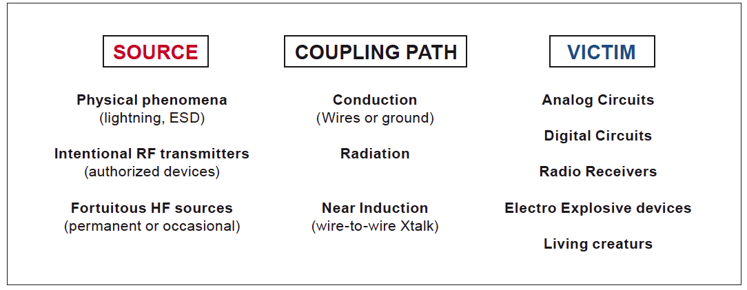
As shown on Fig.1, interference coupling paths can be grossly divided in CONDUCTION and RADIATION. Why and how is this sorted-out? This is purely arbitrary since no current can flow without creating an associated electromagnetic field, and vice-versa, any electromagnetic field is causing voltage and/or current to appear in exposed conductors.
However: Up to a few MHz (say < 10 MHz) conduction coupling dominates EMI problems, because at such frequencies, typical equipments, internal circuits sizes and external cables lengths are << λλ. Remember, wavelength and frequency are related by: λλ(m) = 300/F(MHz). Think that a 1.50m cable length represents only λ /20 at 10MHz, and λ /200 at 1MHz, making it a very unefficient antenna for radiating undesired…
Dear colleague,
This text is unfortunately locked for further reading, but you can read all Michel Mardiguian’s texts and course material about EMC in the new book “Everything you always wanted to know about EMC but were afraid to ask”. Click for more information!
![]()