


Most designers . and installers of electrical equipment agree that shielded cables are a good way to achieve EMC. But many times I have seen big money thrown ”down the drain” because of overconfidence to the cable shield effects and ignorance of its proper use and design.
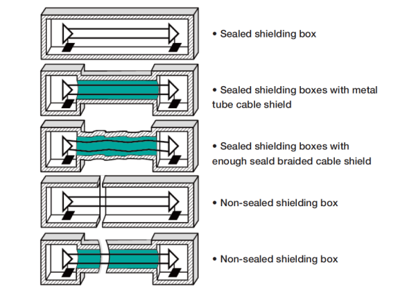
Cable shield is usually an extension of the shield of the devices and are thus part of the overall shield. Apertures in the overall shield means field leakages; therefore we must bond the cable shield to the shield of the device. If the cable shield is intended to be a “link” between two devices, the cable shield must be bonded at both ends to the shields of the devices to keep the entire zone boundary closed and to obtain good shielding (Figure 1).
We should answer a number of questions before we decide on the use of shielded cables:
Can the cable shield be properly bonded? Where is the source of disturbance located? Emission or incident field? The frequency range of the disturbance?
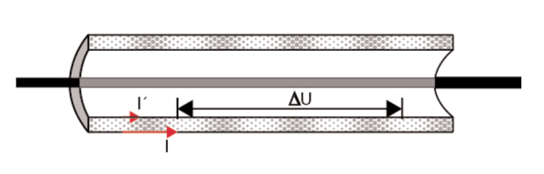
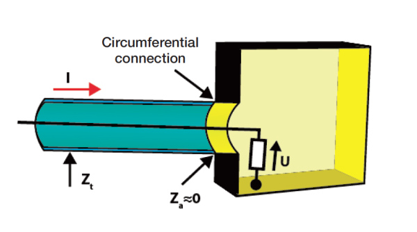
Shielding properties of shielded cables are described with the concept of transfer impedance (Fig. 2). Transfer impedance states in ohm/m the ratio between the disturbing voltage generated inside the shield and the disturbing current flowing on the outside of the cable shield.
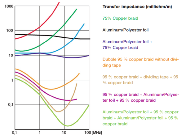
Transfer impedance is a measure of the cable shielding properties. It is frequency dependent and dependent on the materials and design. Typical values are 1 – 10 milliohms/m and some example are shown in Figure 3.
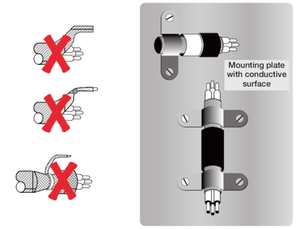
A good cable shield bond for high frequency shielding excludes “pigtails” because the bonding impedance becomes too high and totally dominant in the transfer impedance. We should strive for zero ohms in bonding impedance between the cable shield and the shielding box. An impedance of 10 milliohm of a pigtail leaks as much as one meter of cable if the cable shield transfer impedance is 10 milliohm/m.
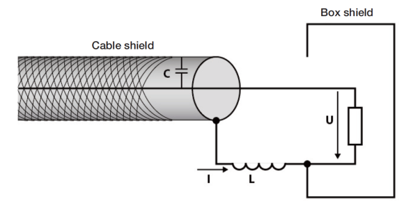
A cable entry gland provides an excellent EMI shield for screened cables which pass through enclosure walls (Fig. 4).
A wire (pigtail) with a length of a thousandth of the wavelength represents approximately 2 ohms impedance, at the corresponding frequency, due to the self inductance of the wire. Use shielded hoods for cable connectors to bond the cable shield to the box with 360 degree coverage.
A generally well functioning way is to connect to the underlaying conducting surface with a clamp (Fig. 5).
In the next article we will deal with low-impedance bonding.
Miklos Steiner and Ulf Nilsson