

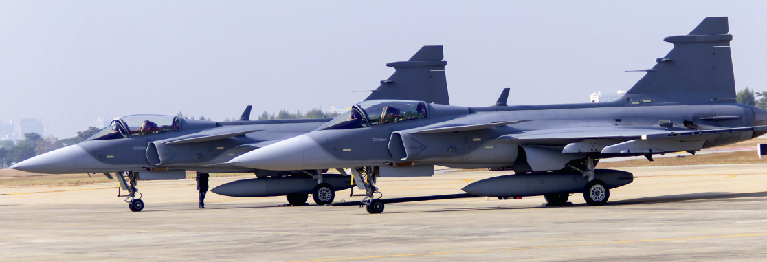
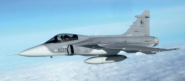
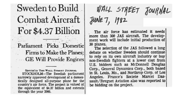
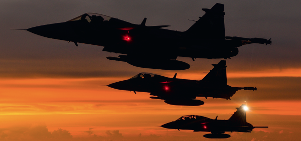
The new version . of the JAS39 Gripen fighter is now a strong competitor in the fighter aircraft world market and the aircraft operates in several countries. A historical review of the early EMC work for the Gripen project may be of interest. The JAS 39 Gripen fighter aircraft project was outlined and presented in 1979-1981 by SAAB Military Aircraft & The Industry Group JAS also including the Ericsson Microwave Co. and Volvo Flygmotor. The development of the Gripen system and a production of 30 aircraft for the Swedish Air Force was decided by the Government in 1982. The decision was made after an intense debate in the media whether Sweden had the competence and capability to continue the independent fighter aircraft development although such projects had become extremely complex and costly.
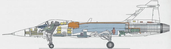
The Gripen system was the first of a new generation fighter aircraft . It was designed with extensive use of carbon fibre composites, CFC. The supersonic very agile and instable aircraft was controlled by a full authority digital fly-by-wire system. A multitude of conventional aircraft instruments were replaced by three multi-mode electronic displays. The engine was controlled by a high authority Digital Engine Control unit.
Gripen had a new tactical radio system, old and new weapons and other tactical systems should be integrated and controlled via data-buses by the central computer. Gripen’s integrated advanced Radar and Electronic Warfare suit with many sensors and transmitters communicated via multiplexed data-buses. The Gripen system formed a new very complex and unexplored technology for Sweden. It was named ‘The first 3rd generation fighter aircraft’. Many companies in Sweden and other western countries were involved in the multi-national ‘Swedish’ project!

The avionics technology had seen a dramatic development during the 1970s’ and 80s’. SAAB was one of the leading companies and had already in the 1960s’ formed the Datasaab Co. where computers were designed and produced for general needs, for the design work at SAAB and for the avionics of the SAAB 37 Viggen fighters forming the backbone of the Swedish Air Force in the 1980s’. Its predecessor the SAAB 35 Draken with the first version developed in the early 1950s’ had been designed with the slide-ruler as the tool for calculations! In 1980 many of the system engineers at SAAB had a high competence from several aircraft projects including the Draken and the Viggen projects. Late editions of the Draken aircraft were still in service during the first years of the Gripen project.
The capability of the EMC group at SAAB had followed the general avionics development. The group had developed new requirements, methods, instrumentation and tools that formed a valuable base for the EMC work at the Gripen development. The review of the 10 first years of EMC work for the Gripen project illustrates the design challenges at the development of a new advanced fighter aircraft system 30 years ago. The author gives an insight in the EMC work of the project from his position in the EMC group at SAAB Military Aircraft during the first 5 years of the project and thereafter from his position as manager of the EMC group of the Testing Directorate of the Defence Materiel Administration, FMV T&E.
The EMC group at FMV T&E represented the defence customer for the EMC quality control of the Gripen project. Several major EME test systems were acquired by FMV for the Gripen testing (Government Furnished Services, GFS). FMV T&E also supported SAAB and the IG JAS at the EMC design work. The first flight of a Gripen test aircraft took was made in 1988 but the design and system test programs for the production aircraft continued. The detailed EMC requirements and technical design of Gripen can for natural reasons not be presented here as such information is classified for commercial and defence reasons.
The Gripen project structure
The Gripen project was formed by more than 20 sub-system projects, e.g. aircraft structure, engine system, flight control, navigation etc. The sub-system projects were coordinated by the Gripen System Design Manager. Although not being a hardware system, the EMC design was one of the sub-system projects and the group reported weekly at the joint system design meetings. The tight communication among the subsystem projects was essential at the very fast and complex design work.
Misunderstandings were avoided, any mistakes could be corrected immediately and design compromises were agreed together. Unavoidable project delays were communicated continuously and extra efforts were spent on the time schedule. The formal structure and documentation of the project work was well organised by coordinated time-schedule and activity plans. EMC had a dedicated position in all documents and at all sub-system activities.

General design parameters were identified for the weight and cost of all components. A specific project cost including project ‘time consumption’, was defined for each parameter. Such aspects had to be considered also for the EMC design as well as any project delay risks. Risk management has traditionally been in focus at aircraft design. The SAAB EMC-group managed the integrated EME-design and coordinated the EMC work within the Industry Group IG JAS. The group got a strong position in the project and were well supported by the management and the customer. That was essential for the EMC work.
The SAAB-Fairchild 340 commuter aircraft project was initiated in parallel with the Gripen project. That imposed a heavy workload on the small EMC group. The civil SF 340 project met a very hard commercial competition with an extremely tight time-schedule.
In the 1980s’ the Viggen aircraft built by SAAB formed the backbone of the Swedish Air Force. Several versions, both the older ‘analogue’ versions and the modern JA37 having a digital flight control system, would be in service for more than 10 years. Signs of ageing due to many flight- hours caused minor EMC problems such as fly-by-voice, transmitter cross-talk and P-static noise. Some up-gradings were still made. The Viggen system generated most of the workload for the small EMC group at SAAB. The initial EMC work for the Gripen program had to be squeezed into the almost full calendar of the EMC-group. Several new engineers were soon included in the group.
Murphy’s law applied
The overall design strategy of the Gripen project stated that Murphy’s law applies – All that can go wrong will do so. The implication was that every design, equipment and integration detail should be kept under tight control. The high quality control ambition was somewhat modified by a message from the EMC project manager to the EMC design team that ‘Our design and quality control work has been over-ambitious if we don’t find any problem at the final system verification tests’.
The conclusion was that a very stringent and well controlled primary design and quality control work was needed that might result in a limited number of manageable EMC problems.
New challenges for the EMC work on the 3rd generation fighter
The aircraft and avionics technologies had seen a period of dramatic development during the 1960s’ and 70s’. In USA Rockwell had developed the B1 Lancer bomber in the 1970s’. In Sweden the Viggen system was upgraded with the JA37 having first generation digital avionics. BAE in the U.K. had developed the Tornado aircraft and in the USA new editions of the General Dynamics’ F16 were developed with upgraded features similar to those of Gripen. The Lockheed F-117 Nighthawk stealth aircraft with an exotic airframe had been developed in the same period. However, the Nighthawk was very secret and it was not revealed to the world.
The development of new generations of air systems had also stimulated the development of new EMC hardware components and design tools. Still, one major challenge for the early Gripen design was the lagging status of several EMC technologies and standards needed for the new fighter. The engineering tools, competences and EMC standards were adapted to electromechanical and analogue electronics and the analogue HF-UHF radio transmitters of the 1960s’ and 70s’. No defence standards were available for integrated air systems EME testing.
The political debate concerning Sweden’s capability to develop the Gripen had created a strong attention on the engineering capability and efforts. The project got a very strong support from the Government and the Defence HQ. The focus was put on quality control, safety, aircraft performance, less on the economic aspects. The attention and support from the top management at SAAB on the engineering work and resources, included EMC, throughout the design and production work.
This was invaluable for the EMC group. In 1980 the office computer power at SAAB was not useful for detailed EM calculations. Much of the early Gripen EMC work during the 1980s’ was spent on exploration of the new Cray-1 supercomputer capabilities for CEM calculations and on the development of the EMC standards, test tools and methods for the high performance and safety requirements of the Gripen system.
The information exchange handicap – Internet and e-mail were not yet invented
A handicap that can hardly be realised today was the lack of the Internet and e-mail that were not invented in 1980. There were no ways to communicate except telephone, facsimile and slow letters. Participation in expert communities and particularly being an active speaker at conferences were the best ways to form contacts with experts from other nations. That opened for an exchange of many unpublished technical reports and documents from foreign authorities and companies. Reports in technical magazines and printed books could be searched and ordered via the SAAB library but that was a slow process. Conference proceedings and their reference lists formed one major source of information.
Many publications of potential great value were not detected in time for the Gripen design work. One example is the very comprehensive ‘Design Principles and Practices for controlling Hazards of EM radiation to Ordnance (Hero Design Guide), NAVSEA OD 30393. The document published in the 1970s’ is very useful both for weapon systems and for air platforms design. It was obtained by SAAB a few years too late in the mid 1980s’. It presents many of the design principles and the background physics that were applied for the Gripen but had to be explored independently by SAAB for the Gripen design. Similar publications particularly devoted to aircraft design appeared soon after that.
The SAAB group – like other engineering groups at that time – had to do extensive advanced in-house technical R&D work for their project needs. The accumulated and structured collection of paper documents at the SAAB EMC office formed a valuable source of information for the project.
The EME awareness formed by several accidents
Several severe EME-related accidents in Europe and USA were related to HIRF, HERO and lightning e.g. the tragic HERO related fire on the USS Forrestal in 1967 and HIRF accidents of several Black Hawks, F16s and a Tornado. Lightning strikes to aircraft had caused several fuel tank explosions. Two lightning strikes in Viggen aircraft had caused one accident and one severe incident in 1978. The accidents had formed a broad awareness of the EME risks and had clearly illuminated the need for a thorough EMC design work for complex air systems and airborne weapons and a need for refined EME protection methods.
The NEMP and lightning communities were separated from the EMC community
Nuclear EMP interaction was a sensitive subject related to nuclear weapons. The NEMP community and their conferences were only partly open and NEMP protection was separated from regular EMC work. European lightning scientists were very traditional and organised their own conferences. Few studies were reported in Europe on aircraft lightning effects. The main source of information on lightning and electrostatic effects on air systems was the annual International Aerospace and Ground Conference on Static Electricity and Lightning, sponsored by the FAA, NOAA and the US Defense.
At these conferences SAAB could report and discuss technical experiments and design issues concerning aircraft lightning and P-static. However, not many general EMC experts participated in these meetings. SAAB decided that an integrated EMC system design work by one group of engineers including all EM effects was essential for the Gripen project. Initially that required contacts with three EM communities. The situation was soon improved when other projects followed the SAAB example.
Interpretation of the operational requirements for the EMC requirements on the Gripen
The Air Force had defined the Operational Requirements of the Gripen system, e.g. tactical functions, all weather operability, system availability, maintainability etc. These requirements had been translated into a System Specification for the Gripen contract by The Defence Materiel Administration, FMV. The EM effects chapter included all relevant EME factors with eference to defined standards and requirement levels. Some effects allowed for an acceptable degradation of the aircraft performance and some maintenance after an exposure.
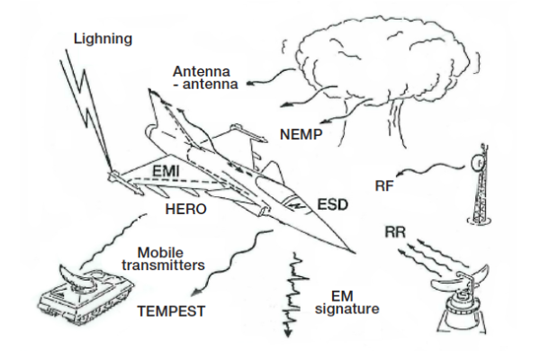
The JAS39 Gripen System Specification formed the baseline for the EM effects design work . It included all EME components, HIRF (radio- and radar transmitters), TEMPEST (RÖS), ESD (P-static) HERO, EMI, EM signature, antenna-antenna coupling, lightning effects and NEMP. In 1981 it was not conventional to include NEMP, TEMPEST and EM signature in EMC specifications. Several EMC groups of the sub-system suppliers were unfamiliar with such requirements.
The EMC requirements as expressed in the System Specification and the Equipment Requirements were based on the known character of the EM environment and the response to it by equipment of the 1970s’. Such specifications were not fully adequate for the Gripen technology. New parameters were needed. One reference in the System Specification was the first edition of MIL-STD-1757 for lightning strikes. It did not include repetitive lightning current pulses. Such stress might impair digital signal sequences. The definition of a lightning strike in the System Specification had to be refined after an agreement between FMV and IG JAS. That had a consequence on several sub-system requirements.
In 1985 the US Federal Aviation Authority, FAA, summoned the international aircraft community to a meeting regarding the HIRF environment. The FAA message was that the very severe HIRF environment near various RF-transmitters had been neglected for aircraft design and verification. The problem applied to the Gripen project and the Gripen HIRF specification had to be revised. The requirement concerning pulsed microwave radiation had to be increased by almost 60 dB in one frequency band! That had a concrete consequence not only on the equipment requirements but also on the overall platform design and on the planned system tests.
The alarm from FAA and the improved HIRF specification created a basic HPM protection of the Gripen. A few years later the extra efforts paid off when the HPM vulnerability of the system was questioned in public media. SAAB could then claim a basic HPM system hardness of Gripen as the potential HPM threat was met by the Gripen HIRF design with its design margin to the HIRF environment.
The international interest and engagement in the EMC design work
The Gripen project was of great interest to other western nations. SAAB had formed a cooperation with Rockwell at an early phase of the project. They had recent experience from the design the B1 Lancer bomber. The contacts with Rockwell also included aircraft EMC but they were soon replaced by a cooperation with BAe in the U.K. for the design and production of the carbon composite main wing.
SAAB and FMV maintained a close cooperation with The U.K. Defence Research Agency at Farnborough. SAAB were members of the Culham Lightning Club that organised lightning research for their members from the aircraft industry and several authorities. The interest by U.K. and BAe in the Gripen work partly originated from their early work on the Eurofighter aircraft, Typhoon. The Typhoon concept included similar EMC technology challenges as those of Gripen.
A first Typhoon demonstrator, EFA lagged a few years behind the Gripen. Also the US Air Force were supportive and arranged several meetings at their main EMC test ranges at Wright-Patterson AFB in Dayton, the Naval Surface Warfare Center at Dahlgren and the US Navy Patauxent River Test Base where a very advanced EM effects system test capability is located.
The NEMP protection design and testing was discussed at the Kirtland AFB and Sandia Labs in Albuquerque where Sweden had good NEMP research contacts via the Defence Research Agency, FOA (FOI). Some of the equipment at the Swedish NEMP test centre was used at the Gripen tests including B-dot and D-dot probes, 1GHz bandwidth transient digitizers with fibre optic links. The equipment design originated from the US Nuclear protection research activities in Albuquerque.
So did the Finite Difference computer codes and the major NEMP test facility at FMV T&E in Linköping.
The Gripen EMC design procedure
A procedure was defined for the transformation of the Gripen System Specification into detailed EM requirements on the aircraft platform, on its avionics and on the tactical functions. The very same procedure is defined in the present NATO document ‘ALLIED ENVIRONMENTAL CONDITIONS AND TESTS PUBLICATION, ‘ELECTROMAGNETIC ENVIRONMENTAL EFFECTS TEST AND VERIFICATION’, AECTP 500 ed. 4.
The AECTP document specifies the steps for analysis of the EM environment of the system, how requirements can be tailored against the functional and safety criticality of individual subsystems and what margins should be applied for each design step. In the chapter ‘Category 505’ the AECTP document defines the verification procedure for air systems and refers to the MIL-STD 464C standard for the detailed EME system requirements.
The high quality of the Gripen work procedure from 1983 that even meets today’s specifications from NATO, was partly a result of the close dialogue with several influential EMC groups in USA and the U.K. The Gripen EMC engineers contributed to the NATO procedures with several elements from the Gripen project by participation in the aircraft community’s standardisation work.
Definition of the EME environment components for Gripen
Much work was spent on the definition of the EM operational environment of the Gripen. No up to date data were available concerning the HIRF environment near powerful Swedish and foreign radio and radar transmitters. Swedish fixed, land-, sea- and ground-mobile stations were analyzed from available transmitter data as a consequence of the alarm from FAA.
Several European countries were contacted and their data were also analyzed for the HIRF environment near high power transmitters. The HIRF environment was mapped for many European transmitters. The radar stations close to airfields was of particular importance.
A detailed mapping was made of the near-field RF environment at some high power HF transmitter sites in Sweden. The measurements were supported by DRA, Farnborough, with their helicopter borne field measuring equipment. The HIRF hardness of the test aircraft had only been proved to limited levels and some restrictions were imposed on the flight envelop. The mapping of the HIRF environment was very useful at the early flights of the prototype Gripen aircraft in Sweden and abroad.
Computational Electromagnetics, CEM – Computer capability and EM design tools
SAAB got the CRAY-1 super-computer in 1983. Going from punchcard and Fortran 4 to Cray-1 was a real challenge. The initial everyday tool for calculations in 1981 was the ABC 800 table top computer. It had a very limited capability and was not suitable for EM analysis. Early support was hired from Messerschmitt Böhlkow Blohm in Münich for analysis of the external EM coupling to the aircraft.
However, the stick model algoritm used was not suitable for EM analyses of deltawinged aircraft like Gripen. The market was surveyed and a few analytical tools were identified that had been developed for the US nuclear program. The Finite Difference EM tool, FDEM, that had been developed by the EM Applications Co. (EMA) in Albuquerque and Denver was the best code available. It could be implemented in the new Cray1 computer at SAAB.
A long term close cooperation was established with EMA in 1983. The FDEM-code had been developed for Nuclear EMP protection analysis. That made them sensitive. The export license from the US Dept. of Energy required much diplomatic efforts. The work was delayed by almost one year. In the meantime the many potential applications of the FDEM-tool were identified. EMA could begin their programming work including several sub-routines and optimization of the code to the Cray1 and the JAS39 dimensions.
Many improvements were made of the code during the several years of joint work by the SAAB and EMA CEM experts. The initial CRAY 1 memory capacity, 1MB, limited the analyzed volume to about 20x30x30 elements which resulted in a poor time and space resolution.
The CAD technology was not yet available and data input was made manually from paper drawings. Any mistake resulted in very odd results. Computer graphics was not yet available in 1983. Primitive matrix printer illustrations (2D-layers) of the FDEM model of aircraft were visualized by a 3D plastic model. The original code was developed for EM coupling of a short transient plane wave. Analysis of lightning strikes required a thorough refinement and new codes were developed for lightning strikes and field diffusion through CFC walls. Some lightning strike analyses including field diffusion through CFC walls required a calculated time span of 1ns – > 10 μ (> 10.000 time steps) with an extremely stabile code and perfectly absorbing boundaries of the analyzed volume. Each of such calculations required many hours of Cray-1 data processing.
Examples of early FDEM analyses for the JAS39 EME project:
- Plane wave NEMP and HIRF coupling to the aircraft. Local fields and skin currents on the external aircraft structure.
- EM coupling to external stores (weapons) and sensors.
- Comparison between alternative lightning test generator designs.
- Lightning current distribution for several lightning attachment points.
- Comparisons between the current distribution for real lightning strike attachments and for various test configurations.
- Correction factors for local skin currents on aircraft in the air compared to aircraft on a ground plane at HF HIRF testing with the current injection – return conductor test set-up.
- Lightning current diffusion through CFC wing walls and the induced local voltages and currents inside a CFC wing and a CFC wing box for testing.
- EM coupling through points-of-entry of various geometries.
The CEM capability of the project has been developed continuously. The group of CEM experts at SAAB has grown since the first years of the JAS39 project. The computer capability has improved and many new codes and applications have been developed. CEM can now replace much of the experimental EMC work. The early code development and later achievements have been presented in many technical reports.
The overall aircraft EMC design – zoning
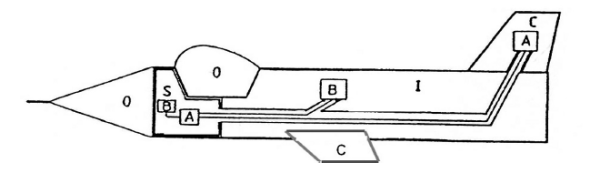
The Gripen aircraft structure should provide a controlled internal EM environment for all installations. The EMC equipment requirements should if possible be kept at ‘conventional’ levels preferably those recommended nominally in the equipment standard of the project, MILSTD 461B. The amount of internal cable shielding bringing extra weight should be kept to a minimum. A zoning concept was established for the project while not yet commonly accepted n the early 80s’. Four zones were defined;
- zone S: a shielded EM environment, providing high attenuation of external effects,
- zone I: an environment inside the conventional metal aircraft providing the attenuation of a normal metal skin,
- zone C: an environment internal of Carbon Fibre walls,
- zone O: an open environment where the external structure did not provide any significant shielding e.g. on the exterior of the aircraft, inside radomes and in the cock-pit area.
The SICO-concept was thus formed for the EMC project work. All structural design measures, installation principles and sub-system/equipment requirements were guided by the SICO-principle.
A well shielding compartment forming zone S was enclosing the vast majority of the avionic equipment. All cabling inside the S-zone could go without external shielding as the S-zone structure provided a > 40 dB shielding to the external environment. That required thorough design measures. Particularly all equipment bay doors had to be designed with conducting gaskets. Frequently opened service doors were provided with extra reliable and enduring shielding measures.
Any compromise of the shielding by external surface mounted components such as air-sensors and electric lights were controlled by EM pointof- entry requirements named RS/RE and RS/CE.
The p-o-e quality requirements were uniquely defined for the Gripen project. The related test method was a combination of MIL-STD 462 emission and susceptibility testing i.e. radiated and conducted emission from internal cabling with the test item illuminated on the external side with RS- requirement levels.
The strict RS/RE – RS/CE requirements controlled all local pointsof- entry for EM fields. Extra design measures had to be taken for some components in order to meet the p-o-e requirements e.g. metal mesh on some external lamp housings and extra shielding of the connectors in the wing pylons.
The shielding continuity between the S- and I-zones was achieved by closed metal walls. All cable ‘feed-throughs’ into the S-zone had connectors with shielding back-cap connectors on the shielded cable bundles in the I- and C-zones. The cable bundle shielding quality was defined for an internal cable environment comparable to that in the Szone. The resistivity and mutual inductance per meter of braided shields were defined according to the location in the I- and C-zones.
Some cables were installed with ‘lossy-line’ cable jackets. The C-zone was characterized by a high shielding quality at high frequencies that did not diffuse through the continuous CFC wing and fin skins. At low frequencies < 10 MHz, EM fields could diffuse through the several mm thick CFC walls making the C-zone shielding less effective.
Lightning protection
Experiments were made at the High Voltage Research Institute in Uppsala on a Gripen scale model in order to define the primary lightning attachment zones. The results were supported by the FAA recommendations for civil aircraft.
One consequence of the very agile Gripen performance was that the avionics and flight control systems had to continuously maintain their full function during and after a lightning strike. A criticality analysis indicated what functions had to sustain induced transients from lightning strikes, their required functionality after a strike and any acceptable consequences for the remaining functions. The refined definition of a lightning strike according to later editions of MIL-STD 1757 included multiple strikes and current burst having a > 1 second duration. All critical functions were tested according to the improved lightning standard.
The fin, the canard wings and the Gripen main wings were designed with CFC outer skins. The wings had a hybrid structure with a CFC outer skin, internal CFC spars, metal ribs, metal tubes for cables and several metallic fuel pipes. The wings also had metallic wing tip rails for EW sensors and weapon pylons and under-wing pylons for tactical loads.
The lightning protection of the main wings formed a particular problem as the wings formed fuel tanks, so called ‘wet wing’ tanks, without rubber lining. One engine fuel alternative was JP4 (MC77) that is highly inflammable. No sparks were allowed inside the tanks and the very complex wing structure had to be lightning protected. The spark free design required very large efforts, basic research work and an extensive technical development work.
An aircraft lightning expert, J.A. Plumer, Lightning Technologies Inc., was consulted for the lightning protection of CFC wing structure. A number of design alternatives were proposed by LTI.
Somewhat later SAAB got the excellent NASA Reference Publication 1008, ‘Lightning Protection of Aircraft’ with J.A. Plumer as co-author. BAe was contracted for the main CFC wing design and production. The lightning protection of the wings was worked out by SAAB in cooperation with BAe engineers. The protection techniques could also be used for the EFA design and the engineers at BAe learned the lightning protection technique from the Gripen and became aircraft lightning experts in the U.K.
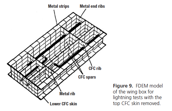
Many FDEM analyses and experiments were made by SAAB for the lightning protection design. Experiments were made at the Culham Lightning Labs. in U.K. on a large ‘wing box’ sample with realistic CFC walls containing all critical internal wing components. Incendiary sparking was initially detected with fibre optic sensors in the wing box at threat level lightning experiments.
After several refinements such sparking was fully suppressed. Detailed production instructions provided the spark-free lightning protection of the wing tanks. It was found experimentally that direct lightning attachment to metal fasteners in the CFC wall of the fuel tanks could produce heavy thermal sparking. Fuel ignitions were demonstrated when a simulated tank with an inflammable gas mixture was tested.
Several alternative protection measures were tested until a spark-free solution was found. The local hot-spot formation on the resistive CFC wing walls at direct lightning strikes might induce thermal ignition of fuel vapours in the wing tanks. Lightning strike experiments were made at the High Voltage Research Institute in Uppsala with real time measurements of the internal skin temperature at full threat lightning strikes. A first generation Thermovision camera was used. It showed that cooling the wing surface with a realistic external air-flow limited the internal hotspot formation well below dangerous temperatures (> 200C) for fuel ignition.
The lightning protection design of the aircraft nose radome was made according to the experience from the lightning protection of the similar Viggen nose radome. That protection had been worked out after the accidents in 1978 that were caused by a poor lightning protection of the pitot-tube heating wires in the nose radome.
The lightning protection of the Gripen cockpit canopy was another challenge. The large Perspex canopy has an internal metalized layer for signature purposes. It is provided with an explosive strip along the top for the pilot emergency ejection. A lightning strike is not allowed to affect the rescue function nor the metallisation. The lightning hardness of the canopy was verified by several lightning strike tests. The protection of many other details were tested against direct lightning strikes e.g. the landing gear and several antenna elements.
Static electricity – ‘P-static’
A well known problem from the Viggen and other aircraft is electrostatic charging when flying in air containing frozen snow particles, called P-static. The voltage generated may be > 100 kV such high voltages produce corona- and streamer discharges from pointed details on the aircraft surface.
The generated EM noise may severely disturb transmitters and sensors. This problem is worst for signals < 10 MHz but also signals at higher frequencies could be disturbed. The Gripen was protected from any P-static problem by eliminating all external isolated metallic details inch and by anti-static paint on dielectric surfaces e.g. the antenna elements.
Experiments showed that the aircraft could do without the P-static dischargers that are common on many aircraft. The static free design was proved by testing with a static particle spray gun that could create heavy charging of insulated objects and dielectric surfaces.
NEMP
The response of Gripen to Nuclear EMP radiation was analysed with the FDEM tool. The induced coupling from NEMP into any apertures was added to the composite EME stress envelop for aircraft cables and equipment. The extra contribution to the composite stress envelop from NEMP was marginal to that from lightning strikes and HIRF. Aircraft components in zone O were tested for direct NEMP effects.
Sub -system and equipment suppliers to the Gripen system
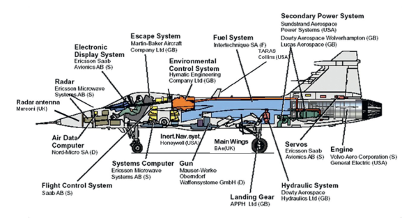
One challenge was to identify and evaluate sub-system suppliers having the capability to design and supply equipment according to the strict quality requirements. The Gripen design work included about 20 sub-system suppliers from USA, UK, France and Germany. After the contracting of the suppliers the next step was to create an efficient cooperation for the detailed, tightly controlled, EMC procedures and to get acceptance from some non-US sub-system suppliers of the requirements specified according to the US MIL-STD 461B with some tailoring for the Gripen design.
Several sub-systems were supplied by Swedish companies. A standardized equipment design concept had been worked out for the Swedish equipment. The standard design included strict rules for the EMC design of equipment casings, grounding of boxes and circuits, external connector installations, filtering and transient protection of power units, signal filtering, the internal box lay-out and a general PCB design. The standard concept saved many efforts for the project.
The EMC design work by the IG JAS partners was reviewed by SAAB. The integration of the radar and the EW suite with the air platform required much joint work. The missile systems to be integrated were government property (GFE). They were not designed according to the Gripen standards and some EMC data were missing. That required extra work and complimentary testing. No modifications were allowed on the missiles and the aircraft interface had to be adapted to their properties.
Many coordination meetings were held at the suppliers of the subsystems. Formal Preliminary Design Reviews (PDRs) and Critical Design Reviews (CDRs) were made before all sub-system tests. The test plans were reviewed and accepted and the EMC tests were witnessed in the labs by SAAB EMC engineers. Some test set-ups were very elaborate with simulators for testing of active equipment. The tests sometimes continued for a long time. The testing by Lear Siegler of the very extensive flight control system lasted several months at the Genesco Lab near Long Beach.
The digital engine control system, DEC, was produced by the original engine designer, General Electric for Volvo Flygmotor. The DEC was installed on the hot side of the engine. Because of the severe environment at the engine it had a very unconventional and seemingly primitive design that confused the SAAB engineers. The DEC technology was considered to be sensitive by GE and US DoD. Little information of its EMC design was provided and the equipment box could only be inspected very briefly. However, no EMC problems were ever caused by the DEC.
The fast electronics revolution during the 1980s’ formed a particular problem. Successive upgrading of TTL-technology equipment with CMOS components and re-designed PCBs should formally have required re-testing in all cases when the compliance tests had been performed on first generation TTL-equipped functions. Many compromises had to be made and in several cases re-testing could be replaced by analysis of the design documents.
The EMC verificati on of the Gripen system
The verification of the Gripen system was managed by a separate department at SAAB. The verification activities were followed and supported by FMV T&E. The EMC testing was performed with close contacts with the EMC design group at SAAB. The group also supported many test activities.
A general strategy was not to accept any system requirements until realistic verification tools and methods were identified. Particularly three EM components, lightning, HIRF and NEMP required extra efforts. The tight project time schedule required a fully available full threat level lightning test system. It was decided that a lightning test system was needed. It had to be tailored to the needs of the Gripen project. The design was supported by FDEM analysis and the Swiss Co Haefely supplied the test system.
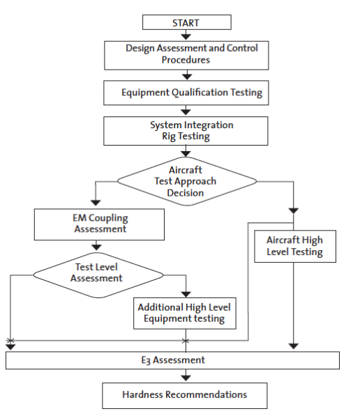
The Gripen EMC certification plan followed a procedure very close to that defined in the present AECTP 500 ed. 4, Category 505. The alternative verification paths shown in figure 11 were followed for verification of the various EM effects. In several cases complementary testing was performed according to both the high level and the coupling measurements verification alternatives.
General principles for EM assessment of the integrated Gripen system
One test approach for system level assessment of the avionics and other electronic functions was to measure the coupling of EM effects into the aircraft S-, I- and C-zones at external exposure. The Gripen system was put in a simulated ‘in-the-air’ status at the coupling tests in order to have the proper signal and power leads connected. The aircraft skin shielding according to the SICO zoning concept was controlled at the system tests. The internal coupling was measured for many cables and the shielding and installation hardness was demonstrated statistically.
That approach was applied for the RF HIRF testing < 1 GHz, the NEMP- and the lightning tests. Measured internal EM signals were corrected for any scaling factors and compared to the MIL-STD 461B / MIL-STD 462 sub-system requirements and laboratory verifications. The lightning coupling tests were performed at the threat level to allow for any non-linear effects.
The threat level MTF system was used at go/no-go testing for assessment of HIRF effects at frequencies > 1 GHz. The tests were made with the Gripen equipment put in an in-the-air mode with the engine running and the aircraft tied in the test position. A pilot in the cockpit observed the instrumentation for any disturbances. He had to wear a metalized suite for protection against the very intense radiation.
The first Gripen test aircraft was tested primarily for its air-worthiness clearance and for a basic functionality for the flight tests. The production aircraft were thoroughly tested for assessment of the EMC hardness quality of the aircraft to be delivered to the Swedish Air Force. Repeated tests were performed when major changes had been made on the aircraft.
Many R&D activities supported the EMC system tests:
- Interpretation of EME factors for modern digital systems, e.g. multiple strike/burst & long duration lightning effects
- Adaption of MIL-STD 462 test methods for the technology of the 1980’s.
- The development of many FDEM algoritms in co-operation EMA
- Design of the lightning test system + FDEM analysis
- HF & HEMP Skin current testing with FDEM support
- EM properties of Carbon fiber composites. EM diffusion through an-isotropic materials
- Ignition hazards test techniques for direct lightning testing including the risks of thermal sparking, electric sparking and hot-spots
- EMC components and cavity resonance suppression techniques for the avionics compartments
- Exploration of the Mode Stirred Chamber test technique for high intensity HIRF testing of external components and missiles (long time before it was standardized):
– General validity of MSC testing (was it hocus pocus??)
– Statistical comparison between MSC and plain wave testing,
– Number of frequency steps required at MSC testing,
– Feeder horn geometry
– Q-value of test chamber
– Test set-up geometry for MSC testing, e.t.c.
EMC
The intra-system EM compatibility verification of the early test aircraft as well as the production version of the Gripen was based on the equipment verifications and the equipment integration controls. System level EMC controls were made on the ground for the air-worthiness clearance. The general system functionality including any EMC influences was controlled at the ordinary detailed flight testing of each produced aircraft before its delivery.
HIRF
RF HIRF testing.
HF-band hardness testing was performed with a current injection test set-up similar to the system lightning tests but with the lightning impulse generator replaced by a powerful CW current injection generator. The HF test configuration had an about 70 Ω input impedance that approximately matched the generator. FDEM calculations were made of the local current density for an exposed aircraft in the air compared to that for the HF test configuration.
Correction factors were applied on any measured values when needed. The aircraft was illuminated locally for RF testing in the VHF and UHF frequency bands. The testing was performed with ordinary generators, power amplifiers and antennas from the SAAB EMC test lab. The coupling into the S- I- and C-zones was determined at several locations for each geometry of illumination.
Microwave HIRF Testing.
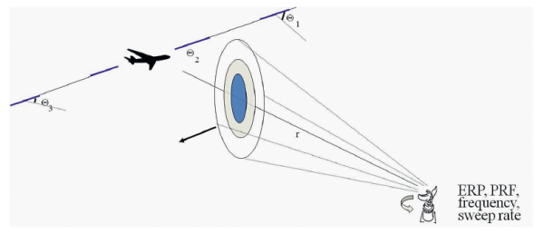
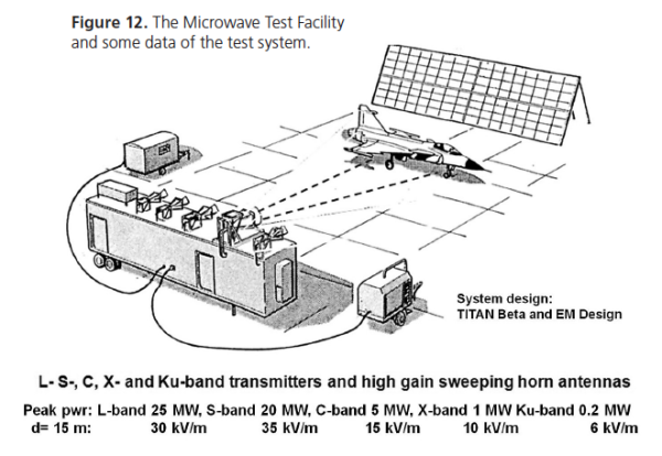
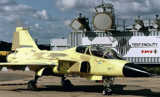
The HIRF protection of the first prototype aircraft was demonstrated for its air worthiness cearance by illumination with a Viggen nose radar and together with several mobile radar stations that were brought to SAAB for the testing with several radar technicians. That test exercise required unrealistic efforts and a dedicated Microwave Test Facility had to be acquired for the planned recurring HIRF tests. Several potential suppliers were contacted for a proposal on the very powerful HIRF test system. The US Titan Beta Co was chosen for the MTF system design with the EM Design Company as subcontractor for the advanced very high intensity illumination antennas.
The overall requirement on the system was to generate the worst case HIRF environment for Swedish fighter aircraft. The capability of the system was limited to microwave sources of five fixed frequencies covering the L, S, C, X and Ku radar bands. They could generate radiation with varying signal parameters such as PRF, pulse length, burst length and intensity. The generator output peak power was 25, 20, 5, 1 and 0,2 MW respectively.
The maximum pulse length is 5 μs. The diagonal horn antenna patterns were decided for a test object distance of 15-25 m. The radiation footprint at the test distance should have at least 10 wavelengths diameter and should well cover any access door of an aircraft. This implied a radiation footprint of at least ca 2.5-3 m diameter. Horn antennas with dielectric lenses were designed to meet the required antenna pattern. The near field limit of the antennas is 12 m or less.
The threat level microwave HIRF tests were performed only at the five frequencies, one each for the L, S, C, X and Ku radar bands. No frequency adjustable generator was available for the extreme output power needed for the testing. Swept frequency coupling experiments on Gripen equipment bays showed a strong frequency dependence. The variations were partly due to a directivity factor and partly due to internal resonances of cavities, structural elements and cables. The uncertainty created by spot frequency testing could partly be diminished by illumination with several angles of incidence.
The uncertainty due to any internal resonances was covered by a good test margin to the external HIRF environment requirement. The Microwave Test Facility, MTF, was designed for the Gripen HIRF testing. It is still in use and has been extensively used by Swedish groups and by other nations for experimental HPM research work.
NEMP
The Nuclear EMP requirements on Gripen included full system threat level testing. In 1980 Sweden decided to establish a large NEMP test centre in Linköping. Its capability should enable NEMP testing of the new fighter aircraft. The Gripen contract did not specify a hardness verification at the planned test facility. The centre was not operable until several years after the formal NEMP verification of the Gripen. The NEMP hardness was assessed by a combination of FDEM analysis, components testing and a threat level skin current injection test on the full aircraft according to the ‘SCIT’ method.
Lightning system tests
A full threat level lightning test was required for air-worthiness of the test aircraft. The focus of the test was to prove the flight safety and the integrity of the basic aircraft functions. The testing of the production aircraft should assess the hardness of all functions.
A threat level system test had been performed by the Viggen aircraft in 1981. The testing was supported by the Culham Lightning Lab. At that time only the thermal effects and the high voltages of the direct lightning current were of concern and the ca 30 kHz dominating frequency of the injected test current was in focus.
However, strong and very fast secondary transients were noted initially in many recordings of internal cable currents. A thorough analysis revealed the importance of the high frequency content of the test current pulses. The findings were reported internationally and the lightning community agreed that the high frequency content at real lightning strikes as well as of the injected lightning current at testing, were of great importance.
The planning of the flight worthiness lightning test was a real challenge. The unique first test aircraft had to be lightning tested at full threat level in a simulated flying mode. The test was not allowed to damage the system or impair its flight worthiness. The test generator was designed in cooperation with the Haefely Co. who supplied and produced the test system according the the SAAB requirements. The generator had a very compact and fast ‘peaking capacitor’ for generation of a fast current impulse and proved to be very efficient for the tests.
The testing was made with injected current pulses having an early full threat peak current derivative, di/dt = 1011 A/s. The peak current was limited to ca 30 kA. Also the charge and energy transferred at each injected test pulse were limited in order to eliminate the risks for equipment and structural damage. A return conductor system was designed for the ‘indirect’ lightning effects testing. It formed an about 70Ω coaxial geometry with the aircraft with the current injection point at the nose pitot tube.
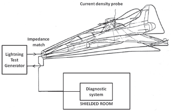
The geometry was similar to the test set-up for the Viggen tests (fig 14). The impedance matching and distribution of the return conductors along the fuselage of the aircraft was refined for high frequency performance of the test set-up while the Viggen test configuration had neglected the high frequency current components. The importance of such effects were not realised until the evaluation of the Viggen tests.
HERO testing
The Gripen missiles were government supplied equipment GFE). FMV was responsible for the EME hardness assessment of each missile. Complimentary EMC tests were performed at the FMV T&E EMC lab for some missing data including the new RS/RE and RS/CE requirements. The aircraft gun was an integral part of the aircraft. Its hardness was assessed at the sub-system level.
The aircraft missile installations were tested for HIRF coupling by use of simulated missiles with a detector installed in each of the ignition circuits of the missile engines. The detector was a non-contact bridgewire thermal sensor with the output signal coupled via a Fibre Optic Link to the measurement system. The sensor and FOL system had been explored and the test method refined by Bofors Co for testing with both CW and pulsed HIRF exposures. The sensor system was just barely sensitive enough for the Gripen HERO assessment including the extra design margin required for ordnance systems.
Antenna – antenna coupling
Swept frequency coupling measurements were made for each antennaantenna coupling path. The measured coupling combined with the measured out of band transmitter emission and susceptibility data from the MIL-STD 462 testing could assess the disturbance free antenna – antenna system design. All transmitter and antenna data were put into a transmitter/antenna database with data for the > 20 antenna elements on the aircraft. The database supported the continued management of the transmitters and sensors development of the Gripen.
TEMPEST and EM signature
The Swedish TEMPEST (RÖS) performance of Gripen and the EM noise emission from the aircraft were controlled in parallel with the EME work. The RÖS and EM signature requirements and the test methods are classified as well as the protection measures. Therefore, no information about the RÖS and EM signature design is included in this survey.
The System Report
The entire EMC design work on the aircraft platform at the sub-system and integrated system levels including all design reviews, analyses and tests were summarised in a Gripen EM System Report for each version of the aircraft. The System Reports list all the design and analysis measures and assessment details with the relevant reports as references. The number of references varied for each version of the aircraft but was about 500.
The System Reports summarized the facts that demonstrated that the airworthiness and performance requirements were met and how that was assessed. Any limitations were clearly stated as well as what influence they had on the aircraft performance.
Conclusions
The Gripen project formed a huge challenge for the EMC group at SAAB. That challenge could be met with the strong competence formed at SAAB together with a close cooperation and support from several Swedish and international technical experts and scientists. The EMC design resulted in an aircraft system that met the ambition goal of the manager of the EMC group at SAAB.
Several deviations were found at the EMC system tests but they could all be corrected. The first version of the Gripen formed a good baseline for the continued Gripen work beyond the first 10 years.
The very stringent methods used at the EMC design work proved to be successful. The technical integration work of the very complex aircraft system could be made without any severe EMC problems.
The Gripen system has been developed with several new versions and the EMC group has grown and been transformed with the system. The pre-computer/IT-age of the early project has been replaced by new high performance IT-systems and instruments supporting the EMC work at the present major system development and for the future versions of the Gripen.
The many challenges of the project resulted in a significant improvement of the Swedish EMC engineering competence including many technical and analytical tools. The procedures and many technical methods used at the Gripen EMC design have been included in many EMC courses and EMC guidelines e.g the EMMA manual for defence EMC work.
K G Lövstrand Technical Director (ret.) FMV T&E, Linköping