

The study . “On the EMC Performance of Cable Trays” started with a contact between EMC Services and the Defem company. Their problem was that their design had been given a lot of criticism in the standard EN 50174-2:2000 (on page 25). The standard was found to contain a lot of formulations on EMC, but there was no rationale for the text – nor were they complete.
When we first were introduced to the Defem type of cable tray system we became quite curious: could this be a good alternative to sheet metal cable trays from an EMC point of view? Could this wire mesh tray, built up with metal wires going in parallel (essential for our thoughts) to cables placed on them, be a “ground” as good as sheet metal?
We had the feeling it could be so because we saw the resemblance to a transmission line (for common mode currents). We also understood that because of the mesh buildup, a more flexible and continuous ground system could be constructed (among other benefits) in an easier way compared to sheet metal cable trays.
This seemed to be a realistic way of achieving a good ground system compared to the regular split-up “non-ground” ladder type of cable trays, as we saw it. The idea for performing the tests described in “On the EMC Performance of Cable ”Trays” was to see if this could be the case.
But then again, what do we mean with the word “ground”? Is it a metal rod driven into the soil at the transformer? Is it a bolt in the bottom of the installation cabinet?
Maybe we are using the wrong word, because we actually want to build a shielding metal structure. So we should use the word “shield” instead? Or at least we should say “ground plane” so that the shape is described.
The principle of ground plane and signal transmissions
From an EMC point of view, power and signal cables should – together with corresponding cabinets – be placed above a ground plane. This ground plane does not need to be much wider than the cable bundles. Compare with the corresponding printed circuit board (PCB) techniques, where the ground plane always shall be larger than the trace routing.
A ground is one of two parts in a transmission line; the “return wire” where the signal current comes back to its origin. A simple type of transmission line is a conductor placed over a continuous ground plane at a constant height together with the signal and receiving circuits, see Figure 1. This is the same technique as in used in PCBs. The benefits of using a well designed transmission line for signal transmission are several: the signal will be transmitted and received as sent (i e no resonances will occur) and the coupling (field emission, field pickup) to the surrounding will be minimal.
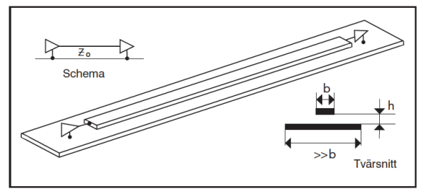
To minimize the coupling to the surrounding it is also beneficial to reduce the distance (height) between the signal conductor and the ground plane.
In Figure 1, the characteristic impedance of the transmission line Z0 is due to the height h and the conductor width d. The ground plane shall be quite wider than the signal conductor. The output and input impedances of the driving and receiving circuits shall have the same value as Z0. The signal will be distorted if the width, height or circuit impedances vary – and increased resonance effects, crosstalk and emission will occur.
In our case – consisting of electronic components, cables, cabinets and trays – it is not the intended differential power feeds or signals between conductors within cables which are of interest; it is the unwanted common mode (CM) voltages and currents which are of interest. It is those voltages and currents that create the unwanted couplings such as crosstalk, radiated emission and pickup of unwanted fields.
The intention is thus to minimize the CM coupling
- between cables (crosstalk)
- to cables (immunity to fields)
- from cables (emission)
by placing them on an high frequency wise high performance, and thus from EMC point of view, cable tray system. Of course, designing and building electrical and electronic systems with a minimum of CM voltages and currents (see below) on cables is the first step, but this is seldom achieved in common industrial systems of today. Thus, the next step to minimize CM coupling would be to implement the RF ground plane technique for the CM voltages and currents then designing and building electric or electronic systems. The simple way to do so would be to implement a ground plane, as good as possible, in the buildup of systems.
The concept of CM and DM
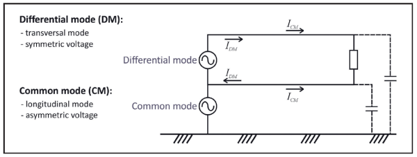
Maybe a short explanation of the CM and DM definitions should be given. Specific for interfering powers and currents are that they can perform in both differential mod (DM) and common mode (CM) unlike a general signal or a power voltage, what only is intended to perform in differential mode. Moreover, CM current can flow without hardwired connection to some return; there is of course always capacitance to the environment. DM voltage is the differential voltage between a pair of conductors (current in opposite directions in the pair).
CM voltage performs with the same polarity and amplitude on all wires in a cable relative to a common reference (ground), see the Figure 2. CM current flows in the same direction on all conductors in a cable (including shields). CM voltage creates no differential voltage between conductors in a cable, unless there is imbalance. There is always an imbalance, and that is why CM currents are regarded as the major problem when working with EMC.
Application to cable trays and the related electronic systems
The idea, which is not new for the EMC community, is to adapt existing cable trays to provide a conducting structure as continuous as possible close to the cables. Due to
practicalities it is more difficult to achieve continuous common mode impedance in cable tray systems, but the goal should be to do so.
In the article referred to you may see that this idea works quite well:
- Traditional cable tray ladders are not providing anything but cable support.
- Trays made by parallel strings (mesh trays) are almost as good as sheet metal cable trays.
- To be of any help for EMC, the cable trays need to be connected together and to the metal cabinets or boxes. Then all types of trays will provide a protection.
- The shorter and wider (or several in parallel) the interconnections (the bondings) are, the better (best high frequency performance).
- If mesh and metal trays are only connected at one end, they will act as amplifiers of disturbances.
By making low impedance (wide and short) electrical connections between the metallic members of the system there are also other benefits achieved:
- Electrical safety due to low resistance between all electrical parts in the system. Actually, only one connection is needed from a system built like this to the ground point (rod) at the feeding power transformer. However, all electronic systems will mostly have a separate safety ground wire (PE) anyway. But no extra equi-potential bonding wires are needed since the resistance of the cable tray system will be far less than such a conductor (maybe some labeling will be needed, but that is a safety issue that we are not experts on).
- The proposed RF shield structure (which is the EMC label for an equi-potential grounding system) will work for relatively high frequencies. That means that it also works for low and medium frequencies, including transient phenomena such as lightning. If the industrial site has a set of over voltage lightning protection (OVP) devices, the function of these will depend on the existence of a low impedance ground reference. If there is no ground plane, the OVPs will be hanging loose in the air and do no good. The RF shield structure (trays and cabinets combined) will provide this critical support. It is mentioned above that trying to reduce CM noise is basic. How to do so? Well, it is not the place to tell how to design circuits for creation of little CM, but in the article it is mentioned that cable shields, if used, should be connected very well to the cabinets or boxes – at both ends – with high RF quality.
Who is using this technique – no one ?
We mentioned above that the described technique is not new to the EMC community. What´s new is that the tests and experiments performed in the article have not, as far as we know, been performed before. Although other types of tests in this field have been performed indicating the same conclusion:
Build cable tray systems as ground planes and make all connections between tray members as short and wide (one wide or several parallel connections) as possible.
Our wondering is why people don´t use this simple and cost saving technique in the industry?
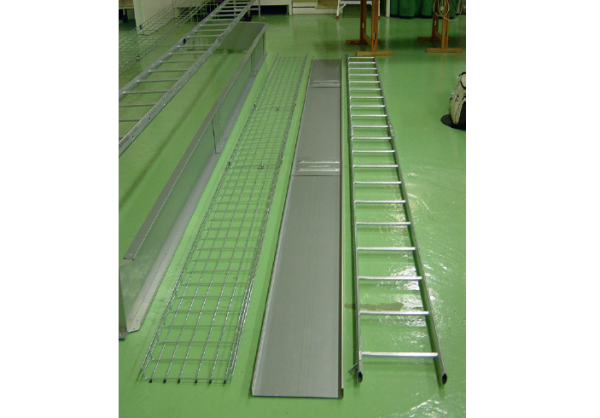
Defem wire mesh tray, Stago metal tray, and Wibe ladder tray.
Why bother about this at all ?
Now, if very few industries areusing the possibility of making a high frequency low impedance shield for their systems – by using the cable trays – things seem to work anyway? So why bother? The reason why it – mostly – seems to be working today may be a number of things, here is a short list:
- The users do not realize that they have interference, but communications are very slow for some reason.
- For all its drawbacks, the CE marking have created improvements and set a minimum level of EMC performance of apparatues.
- Experienced product designers do not trust the electricians who make the installations. They add extra precautions and test for worst case – unprotected cable installation.
- For a long time, the industrial electronics has been allowed to emit about 10 dB extra emission (compared to domestic use), since the use of radio communication (broadcast radio mostly assumed) is not regarded critical and therefore not worth the same protection as in domestic environment. This will work anyway if you have the margins on your side.
So if it is working today (at least we would like to think so), why shouldn’t it keep on working? So again, why bother? Well, the absence of problems in the future would be based on a set of assumptions – and will they hold? Again, a short list:
- All product designers will be just as skilled and experienced as before, and remember all historical previous problems – maybe…
- All electronics will be working in the same way as today, business as usual – but that means that there will be no development…
- Radio communication is not going to increase, we use cables still – but the reality is the opposite; ”wireless industry” is a big slogan…
In short, electromagnetic environment is not a static situation – it is constantly evolving. But in industrial locations, old equipment is always mixed with new technology – and now we are starting to mix new radio communication systems with old, high RF (radio frequency) emitting existing equipment. New sensor technology is also a feature. So what will you do if you encounter problems with your noise margin for the new system? The solutions could be:
- Throw out all old equipment and start all over again.
- Increase radio output power (if you have a loud kindergarten, the teacher need to shout louder).
- Use improved communication protocols, works at least for transient phenomena.
- Use the existing installation material, and combine it to a low impedance shield that reduces the field from old equipment inside the shield.
- Our paper describes the last bullet in the list. We think it is worth trying. Which one is the cheapest? Which is the most effective one?
Who should bother and how?
If the technique of shielding by use of the installation material is not used, it depends on that the stake holders in the industry are not acting on it.
Education
To begin with, EMC education is not mandatory in any type of Swedish college education, not even for electronic engineering. So, tray designers get to know even less, not to mention the installation electricians. EMC aspects on industrial installations is not very sexy for a Ph. D student either, they tend to focus on complex mathematical calculations – which is very good and needed, but not in this problem.
Authorities
To our knowledge, the authorities (like Elsäkerhetsverket) are focusing on monitoring CE-marked equipment and also to make inspections on premises where there are complaints. This is all very good and needed. But when it comes to EMC requirement on installations, the EMC directive in itself is very vague – giving very little support to the authority on how to monitor compliance. What is a “good engineering practice” in installation?
Our article could be a supporting piece that the authority could use to provide guidelines to the industry. This could be the most effective way to reach out to the industry with relevant information.
Standardization organizations
From what we have seen, standardization has been focused on several aspects – but not the ones we have presented here. There is a new version of the EN 50174 series emerging, but we have no new knowledge of this. However, since the standardization is brought forward by the industrial stakeholders in the particular field, it is most likely to be governed by their interests and knowledge. However, with a new version it will be possible to take new steps of improvements if a dialogue with the EMC society (such as IEEE EMC) would take place (which is not the case today).
Industry owners
Since the industry hires persons that have been educated by the universities and other schools, they will only achieve EMC knowledge on their own based on corporate activities. There is a risk that industrial EMC design is based on traditional principles which are not supported by EMC professionals of today. Since there are so many other aspects of industrial buildings, EMC is often doomed to be of low priority. If EMC is addressed, it is often directed to the use of equi-potential bonding (with the use of long wires that are useless at RF) or the use of cutting off the cable shield on cables (which is also wrong). The industry needs updated knowledge.
Component suppliers
The suppliers of installation material are not used to RF principles. Shielding is not a part of the game. They need to look outside their own products (which are sub-parts of an installation) and realize that the EMC performance is governed by the entire installation. You cannot make a good fix in the middle.
Final words
We, the authors, still believe that there are vital improvements that can be made in the industry – and it does not need to cost a lot of money. But the knowledge on how to do it fades away in the abundance of rumors, myths, and old traditions. So maybe we should apply the kindergarten methodology – we all shout louder? But we would like to see an improved communication instead.
Ulf Nilssonemculf@gmail.com Lennart Hasselgren, EMC Services
lennart@emcservices.se